


 |
 |
 |
| Home | Research | Delivery | Empennage | Wings | Fuselage | Finish | Engine | Electrical | GRTDecode | Previous|Next|Latest |
| Electrical | Avionics | Panel | Wiring | Decals | PCBs | ANR Upgrade | |
Avionics | |
Wed 14 September 2005 | |
| Also spent some time on the phone today talking with Stein Bruch from Stein Air Inc who I'll hopefully be using for much of the avionics and panel supplies. A useful session, some guidance on good / bad / options and he is due to get some numbers back to me in the next couple of days. Then I need to get and order in so that I'm not delayed when the time comes. This will be the last 'major' expense (airframe / engine, prop / avionics - roughly 1/3, 1/3, 1/3) then it is all the 'bits' and paint work etc. | |
Tue 25 October 2005 | |
| Meanwhile I looked at a shelf for some of the avionics. Currently we don't know the exact shape / size because we haven't got the parts yet (probably about 6 weeks away). However I do know that some instruments need to be mounted level and in line, therefore some preparation can be done. This is a sheet of 0.040" (slightly thicker than most of the AL sheet that we generally use) and will get precision drilled for the cockpit ribs and folded for strength / stiffness. | 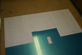 |
| This was the first fitting / location check - should work well. | 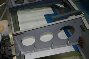 |
| Then it was bending the forward edge. In preference I would prefer to clamp the main surface and bend the tab, however clamping the surface was next to impossible so I had to clamp the tab. This resulted in a bit of mild 'hammering' marks but all came out in the end. | 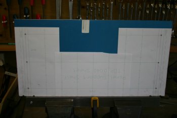 |
| The stopping point for today. The outboard edges and aft edge all need to be bent, but I'll wait for some of the instruments first in case size / layout makes a difference. | 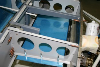 |
Thu 17 November 2005 | |
| GRTDecode - Over the past couple of weeks I've been working on a utility to decode the GRT EFIS log files to XML so that information can be extracted and used as desired. Today I've released it to the wild and published links on the GRT Yahoo group and vansairforce boards. Details can be found here | |
Mon 09 January 2006 | |
| I spent most of the afternoon sorting the VOR antenna mounting, after various options I decided to try a single U shaped ledge. After some careful measuring and designing I ended up fabricating a shelf from a piece of .032 sheet. | 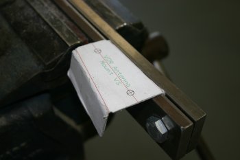 |
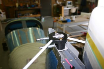
| This is the result. The clearance is about 1/4" to the counter balance and well clear of the skin. | 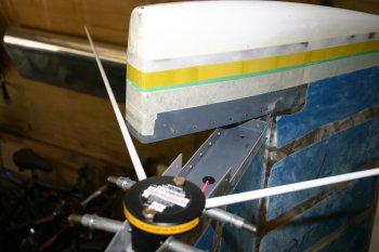 |
 | |
Tue 10 January 2006 | |
| Continuing with the VOR antenna mount I needed a AN3 nutplate jig. We didn't get the larger versions so I spent a bit of time making acurate steel templates, these can be used with a bolt for locating. | 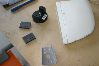 |
| Once we confirmed the bracket would work for the mounting, I started modifying the fibreglass tip. | 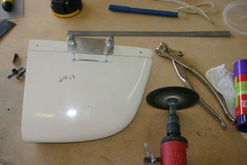 |
Wed 11 January 2006 | |
| I went back to the VOR antenna mount, after more thought I decided it wasn't right (the forward fold was about 1/16" out) so I modified the CAD drawing and made a second mount. The CAD drawing system works well, it provides a good way of 'tweaking' designs, then it is just trying to get the two folds accurately to the marks. | 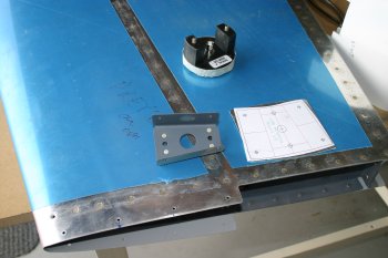 |
| The second time worked like a charm, then it was deburring, dimpling and fibreglass shaping. Then final solution seems to have come out really well, I'll wait until the VS is mounted back on the fuselage to be sure. I'll probably need to make a backing strip for the nutplates and I also added a second pair of screw locations. | 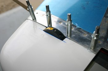 |
Thu 12 January 2006 | |
| I made a backing plate for the VOR puck / VS tip. | 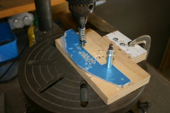 |
Sat 28 January 2006 | |
| Also been emailing with GRT and Stein - today got confirmation that the GRT units are nearly ready to ship. All systems are now go, so hopefully within a few weeks we should have our avionics. Still not sure about the layout yet, and some decisions to be made / information collected, but at least it is progress...... | |
Thu 02 February 2006 | |
| Other things going on today include more planning / organising of electrical parts / bits from the USA - not difficult, just logistics and time consuming. | |
Fri 24 February 2006 | |
| Sorted the VS tip plates - now ready for a flox bonding when I'm next doing some resin work. | 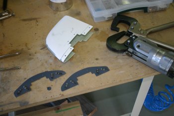 |
Fri 17 March 2006 | |
| Dad got various bits done, including riveting the VOR mount for the VS. |  |
Sat 18 March 2006 | |
| Spent a couple of hours sorting locations and drilling for the two COM aerials on the under-belly. This is in the 'second bay' from the outboard edges and about 8" behind the main spar. | 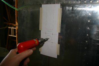 |
Wed 12 April 2006 | |
| Wanting something a bit different and only having a half day, I unpacked all the GRT wiring and started the reading process. |  |
| Knocked up a temporary mount for the MFD's and now understand a bit more of the wiring - generally VERY impressed with the wiring colours and layout for the GRT, well thought through. |  |
Thu 13 April 2006 | |
| Got it powered up - very pretty. Move the AHRS and the picutre changes! Also started looking at the configuration options and updated the fireware to the latest rev's. |  |
Mon 01 May 2006 | |
| A slow day doing bits and bob's after seeing my UK friend to the airport. Whilst in town I picked up a compact flash / PCMCIA interface and 128MB compact flash for the terrain database. | 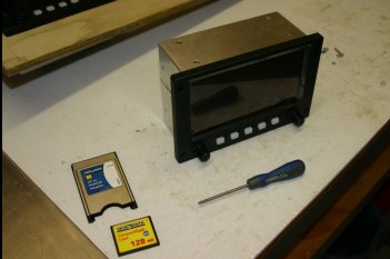 |
| Fairly easy to do the install, just a few screws, but the AL case is really sharp from the pressing - tidying up needed - lighter faster.... | 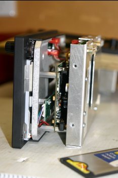 |
| Also spent a couple of hours making a serial cable for use with Scott's MS FlightSim GRTBridge so I can try and learn how to drive the MFDs before I fly it for real. Seems to work OK, but a little problem with the GPS feed for southern hemisphere. | |
Sat 13 May 2006 | |
| I finished the afternoon removing the MFDs and making a wooden panel shell to hold them. | 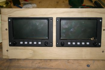 |
| After a bit more configuration and the new updates from Scott for GRTBridge, I've now got the MFDs working with MS FlightSim. Along with the RV7A model I've got most of the bits lined up to be able to play with the MFDs. Already it is interesting to learn some of the common combinations, but it is going to take a bit of getting used to for the airspeed / altitude primary reference. Note the terrian data on the RHS screen. | 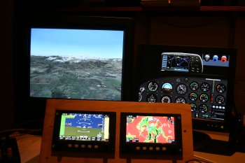 |
Sat 20 May 2006 | |
| Partial day, more research and layout for the panel. I also got round to putting together the CO detector kit. Seems to detect white spirit and other vapours - more testing later. | 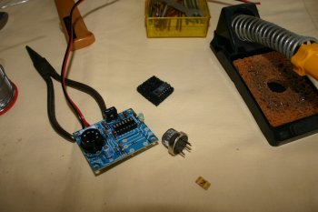 |
Sat 27 May 2006 | |
| Another item on the list is the cut out in the forward sub panel for the avionics stack. I've decided to make a stiffener / plate, this is designed to go around the SL30 and GNS430. The dual vice system worked well again. | 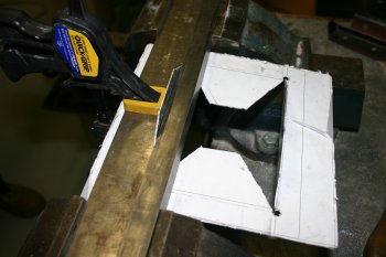 |
| Amazingly it worked and fitted first time! Now I just need to get this mounted / aligned in the right location on the sub-panel. | 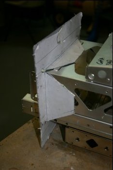 |
Sun 28 May 2006 | |
| Continuing with the avionics rack mounting - the next step is a large cut-out in the panel sub structure. After various options I decided to go with a slightly oversized hole with two folds (inboard and top), the stiffener plate can then go in from behind. | 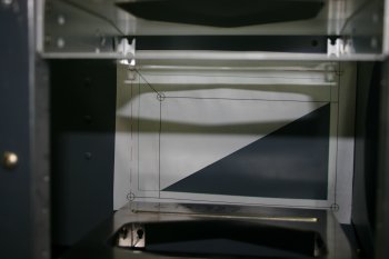 |
| The corners were drilled and the dots joined with the air sabre-saw. I used a wooden block to reduce the flexing in the panel material. | 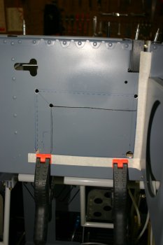 |
| The rough cut, then filing, sanding shaping. | 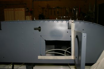 |
| Doing the folds was a bit of challenge, some box section steel and various clamps were used and actually worked very well. | 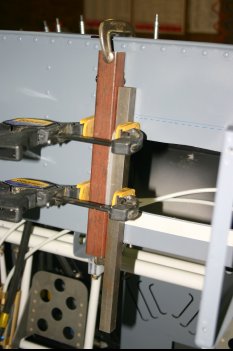 |
| A bit more trimming and the basic structure fits, now it is refinement and making sure everything is square / aligned. | 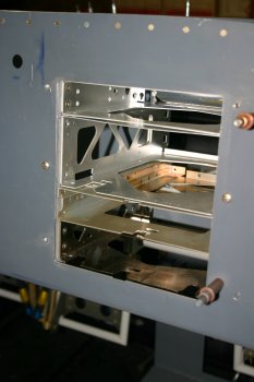 |
| The rear panel with the stiffener, the edge clearance was a bit tight and needed tidying up. | 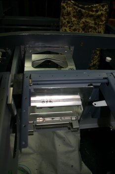 |
Mon 29 May 2006 | |
| More trimming of the main sub panel and then alignment of the frames. | 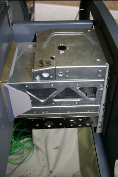 |
| The stiffener could then be drilled and match drilled. | 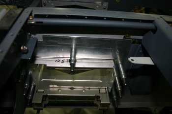 |
Tue 30 May 2006 | |
| The 340 audio panel and 327 transponder both need D plugs through the sub panel - cutouts were made in both layers. | 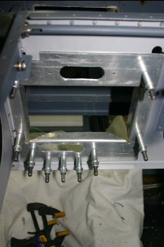 |
| To provide more support for the forward end of the rack (the back of the instruments) I sorted two straps to hold together three of the units. The SL30 rack need two .032 shims (one each side) to get the alignment right. The 430 doesn't have a location pre-drilled here, so.... | 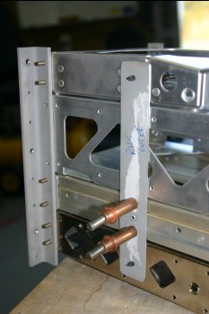 |
| A new location was added at the back of the 430, this was then match drilled to the sub panel stiffener, openned to #27's and dimpled for #6 screws. This also provide rear support for the whole stack. | 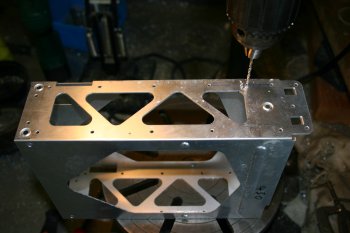 |
| The complete system, very solid and should work well. The access hole for the audio panel needed openning further and the strap will need a couple of tweaks but basically ready for finishing. | 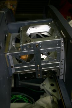 |
Fri 02 June 2006 | |
| Cleaned up and rounded the stiffener plate. | 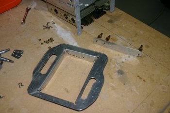 |
Sat 10 June 2006 | |
| Also sorted the VS tip (been on the list for a while, waiting for a batch of flox) | 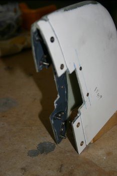 |
Mon 19 June 2006 | |
| As always - new toys - got to play! Removed the back of the module bay on MFD2. A couple of jumpers to remove, install board and close up. | 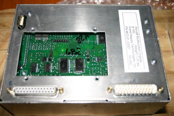 |
| Configuration is on serial 1, 4800, NEMA format - setup on GPS2 for us. Had to disable the Virtual GPS2 and once everything was together I got the diagnostics screen to see the GPS unit but it was late and no position data because the aerial was inside. More testing tomorrow. | 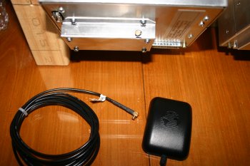 |
Tue 20 June 2006 | |
| Early morning - cold but dry outside, everything works and the GPS2 is seeing enough sat's to get a good position / information. One more piece of the puzzle..... | 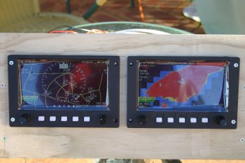 |
Wed 28 June 2006 | |
| The afternoon was spent digging more into the electrics and in particular the GRT EIS4000 unit. After more testing the Aux1 and Aux4 chanels seem to be complete un-usable - some questions have gone out to VAF and GRT. Update: Got an email from Sandy @ GRT 29/Jun/06 - this is normal for a FADEC version of the EIS - it is a feature.... I wish I had the documentation before I spent 3 hours trying to work it out! | 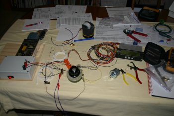 |
Thu 13 July 2006 | |
| Dad was back out on the project (weather was better today) and started on the GRT magnetometer mounting. After various options, rear deck, behind the baggage compartment were discounted, we went for the left hard wing tip. A quick CAD drawing and then drill and bend up. | 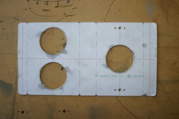 |
| The two vice + stock steel is working well as a bending brace. | 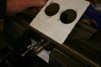 |
| The initial shape including a couple of nut plates. | 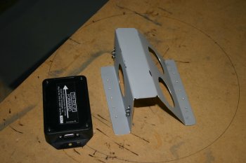 |
Fri 14 July 2006 | |
| Dad spent some time getting the new bracket aligned and drilled. At this point only #40, we will open to #30s once the wings are mounted back up. | 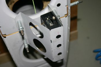 |
Mon 14 August 2006 | |
| Short day, but I did make a final decision on the main GPS antenna location, basically right of centre line on the after upper skin. |  |
| It should have a good sky view from back here and no other transmitters to worry about. |  |
Thu 07 September 2006 | |
| Continuing with some termination I worked my way around the fuselage ends of the coax cables. One thing I didn't realise to start with was the center pin 'pops' into the seat - luckily it was spoted early. | 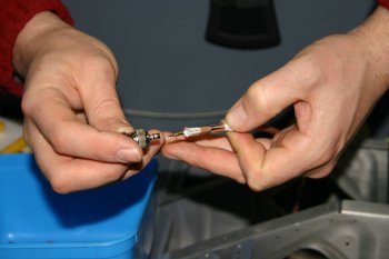 |
Fri 08 September 2006 | |
| Then moved onto the audio cables - lengths manipulated and striped ready for soldering. | 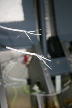 |
Sat 09 September 2006 | |
| First up was soldering the 4 audio jacks - fiddly but OK. Sleeve - Common (Audio Low), Ring - Right / Mic Signal , Tip - Left / Mic PTT. | 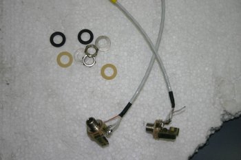 |
| This is the installed locations - just outboard behind the hip. | 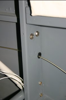 |
Mon 11 September 2006 | |
 | |
Mon 18 September 2006 | |
| The avionics bundle was next on the review list, the biggest problem is the CDI/OBS bundle - about 12" too long. | 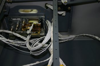 |
| After some debate on the good/bad points of modifying the Stark harness I decided it was the only real option, bell out the connection / documented and then set to with wire cutters. | 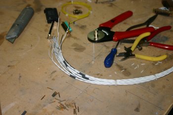 |
Tue 19 September 2006 | |
 | |
 | |
Sat 07 October 2006 | |
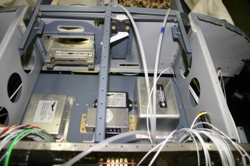
| Then onto the avionics tray - decided to go for the layout that we identified a couple of days ago - need to make progress. |  |
| All the nutplates were back rivetted, read to install. |  |
Tue 10 October 2006 | |
 | |
Wed 11 October 2006 | |
| I finished the afternoon with some simple bits, mounted the NAV diplexor for the GNS430 - it doesn't have one built in - which splits the raw NAV signal into glide slope and VOR components. |  |
Mon 16 October 2006 | |
| I then got the main panel out and mounted up the GRT MFD screens. | 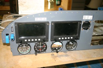 |
| This enabled the start of a cable harness for the GRT components - a large chunk of the afternoon was taken with documentation / planning / organising. This is the back of MFD1 and 2 with the ARINC module in MFD1 (RHS in photo) | 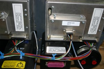 |
| Then onto to avionics stack - I mounted the freshly painted side rails and hopefully installed the rack for the final time. | 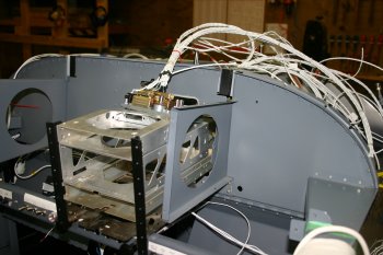 |
| The mounting of the rear plates of the avionics was a bit of bear - very tight / fiddly work. | 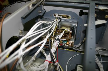 |
Wed 18 October 2006 | |
| After more thought about the mic connections and possible marginal cable lengths, I ended up with a traditional approach. Cutting / terminating lines plus the normal documentaiton. | 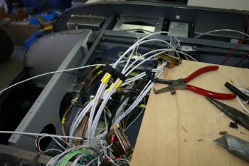 |
| I completed cable routing and started some of the lacing to hold everything. If I was doing it again I might enlarge the mid-panel slot behind the audio panel a little more. | 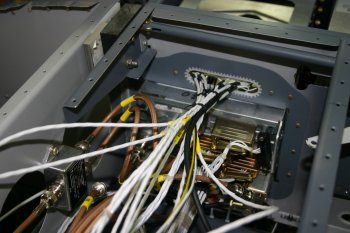 |
| To finish the day I worked throught the avionics data lines. I've got the various data lines from the GNS430, SL30 and GTX327 all being terminated in one DB25 which I can then plug into for the GRT, TruTrak and switching components. Just makes some of the connectivity a little easier to work with. | 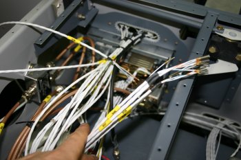 |
Fri 20 October 2006 | |
| Woke up in the middle of the night and realised I'd made a mistake with PushToTalk lines. It needs to be split out for the stick PTT, so undo the GMA340 shells again and reterminate and solder additional lines in. | 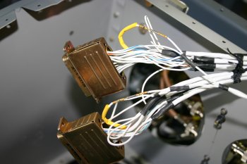 |
| By dropping the cross bar down, I gained access for the 3 nutplate locations which will hold adel clamps for the main bundles of wire. Drill, dimple, rivet. | 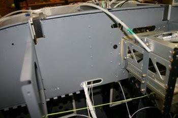 |
Mon 23 October 2006 | |
| Started looking at the GRT avionics harness, both power and signal lines. I took a while to come up with a neat wiring plan and utilise the coloured cables supplied by GRT. | 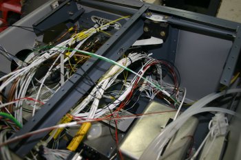 |
Tue 24 October 2006 | |
| With the measurement done, I re-worked the harness and bundling. | 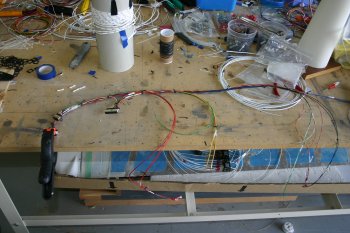 |
Tue 31 October 2006 | |
 | |
Wed 01 November 2006 | |
 | |
 | |
Sat 04 November 2006 | |
 | |
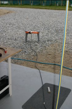 | |
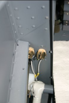 | |
Sun 05 November 2006 | |
| Everything basically working, auto pilot ARINC feed still got some questions about. Fixed the GTX327 altitude encoder feed - mistake in configuration - the documentation was right this time. | 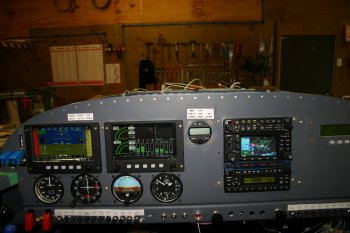 |
Mon 06 November 2006 | |
| Also modified the data lines for the MFDs so that both have a direct GPS Aviation feed from the GNS430. | 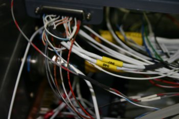 |
Tue 07 November 2006 | |
| Then connected up the AoA system box, power, ground and control lines. The final step was the crimping of the LED ribbon / board. | 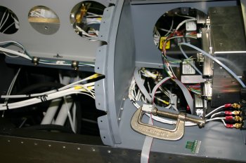 |
Wed 08 November 2006 | |
| After some testing of the AoA I found the upper most red LED was dead. The LEDs are mounted on a mini-board which makes checking / replacement simple. An email sent to Rob @ AFS, hopefully I can get a replacement simply. Update: After confirming I'd done the obvious tests Rob has dropped a new one in the post for me. | 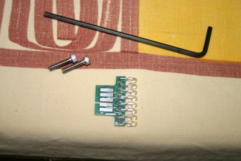 |
Thu 09 November 2006 | |
| As an experiment I re-attached the SBC serial out to the EIS feed, firstly on the A line then the B. Still no go, however accidently the A line grounded on the fuselage and everything sprung to life. This is a 'maybe' solution, I'll need to talk with Jabe @ AeroSance, I don't think pulling one of the data lines (A) to ground is a good long term solution. It is really nice to see the EIS / MFDs working wih engine data however. Also noted some slightly strange temperature numbers on the MFDs (degrees C vs degree F) - questions for GRT. |  |
Sat 11 November 2006 | |
| Also tested the GTX327 power pins. The transponder only has 'soft buttons' for power and has two 'modes'. With pin1 wired to the power line the transponder comes on to standby as soon as the master is switched on, with pin 1 disconnected it doesn't power up until you manually select the 'on' button. After more thought I went back to the original Stark configuration with pin 1 wired. | 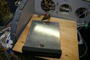 |
Mon 13 November 2006 | |
| I worked on the PTT connections and various tieing. | 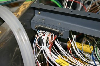 |
Tue 14 November 2006 | |
| I spent most of the day sorting the circuit diagrams / designs and the alignment plate for the 'control' switches. | 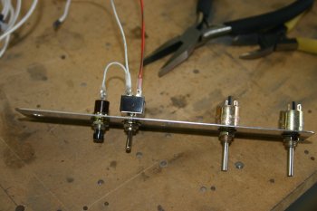 |
Thu 16 November 2006 | |
| I spent most of the day laying up / terminating the electronics bay cables. Also ran some of the remaining annunciator lines. | 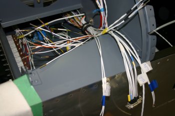 |
Tue 21 November 2006 | |
| Started by trimming / shaping the VS tip for the VOR puck. This was needed after the AL stiffener plate 'oozed' during flox / riviting. | 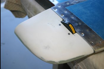 |
| Dad drilled, cut and terminated the mini-coax for the VOR puck. We used snap bushing top and bottom and will restrain the bottom to stop it bashing the inside of the VS. | 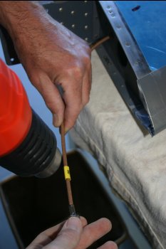 |
Fri 22 December 2006 | |
| One thing that has been worrying us was the autopilot cable bundle. We got 25' from Stein, I've maybe 'wasted' 1/2" and we are about 1" to 2" too short on the wing servo! Do yourself a favour - order 26'! | 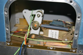 |
Sat 20 January 2007 | |
 | |
Mon 22 January 2007 | |
 | |
 | |
 | |
Tue 23 January 2007 | |
 | |
 | |
Thu 25 January 2007 | |
 | |
Tue 30 January 2007 | |
 | |
Wed 31 January 2007 | |
 | |
Thu 08 February 2007 | |
| First up was trying to find a new route for a 1/4" cable from the RHS of the panel to the tail turtle deck for the ELT remote line. The forward bit was ok and the tail section was obvious. The transition through the spar and into the ducting was not so easy. The final solution ended up going through the RHS tunnel location on the spar, then outboard, round, across and through the tunnel and then aft with the strobe lines. Maybe not he 'best' solution, but everything else is already laid in - and isn't going to change. I think it will work fine, glad I got the extra few feet - 25' was just enough. | 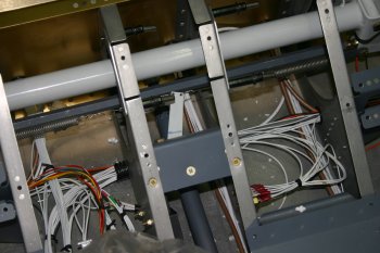 |
Fri 16 March 2007 | |
| I added a diode to the flap sense link on the AoA. | 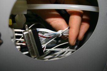 |
| Dad continued with the ELT beefing up of the rear turtle deck. | 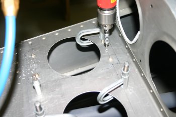 |
| It is pretty simple, two lengths of .063 angle across the turtle deck - the CAA requirments are fairly tough - no more than .1" deflection under 250lbs pull in any major axis. | 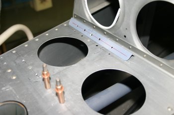 |
| The 406Mhz ELTs have a dedicated warning buzzer on activation, this seems like a good location. |  |
| The location before finishing - wiring still to be completed, I'll get a DB15 shell from Stein on the misc clean up order rather than fighting with soldering plugs together. | 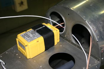 |
Wed 09 May 2007 | |
| More wire tieing / tidying. Very slow but needs to be done. | 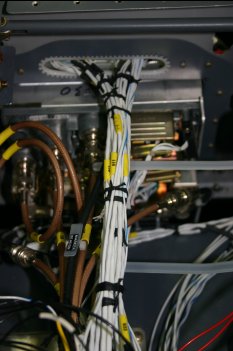 |
Fri 11 May 2007 | |
| Spent the whole day in the forward bay, working around re-bundling / tieing - very SLOW! | 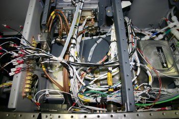 |
Sat 12 May 2007 | |
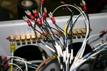 | |
Sun 13 May 2007 | |
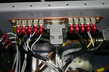
| Worked though all the avionics grounds, re-tieing, re-terminating where needed. | 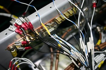 |
Mon 14 May 2007 | |
 | |
Wed 23 May 2007 | |
 | |
Thu 24 May 2007 | |
| Dad terminated the ELT DB15 plug. | 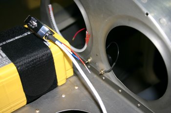 |
| Then picked a lotation for the aerial - this will need a doubler plate / work from inside the fuselage. | 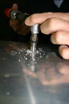 |
Fri 25 May 2007 | |
| I climbed into the rear fuse section and drilled / back rivetted a doubler plate for the ELT and RTV'd the static port connections. | 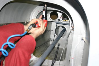 |
Thu 27 September 2007 | |
 | |
 | |
 | |
Fri 05 October 2007 | |
 | |
Sat 06 October 2007 | |
 | |
Mon 08 October 2007 | |
 | |
Wed 14 November 2007 | |
 | |
| Home | Carl Morgan | Previous|Next|Latest |