


 |
 |
 |
| Home | Research | Delivery | Empennage | Wings | Fuselage | Finish | Engine | Electrical | GRTDecode | Previous|Next|Latest |
| Engine | Firewall Forward | Engine Build 1 | Engine Build 2 | FADEC | Baffles | Plenum | Cowling | |
Baffles | |
Thu 01 September 2005 | |
| The first step was to unpack and identify the various parts. I seem to be missing the #9 baffle which covers the forward RHS section (#2 cylinder), I may have to wait until the next order from VANs to get it. | 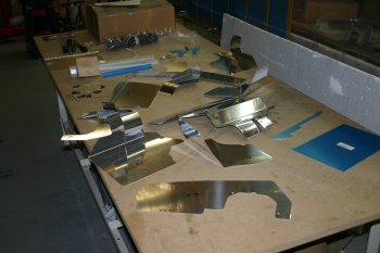 |
| These are the major components laid out, nose towards the bottom of the picture. Then it was the slow process of giving every part a once over with a file and scotchbrite wheel. This got rid of the worst of the sharp edges but I want to wait until I have a final shape before spending too much time finishing. | 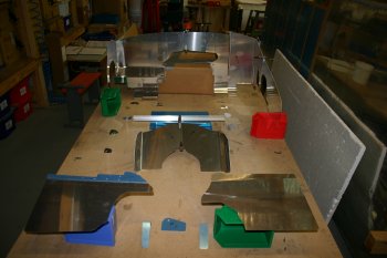 |
| This was the first fit / mock up on the engine. Out of the box the baffles fit OK out of the box, but will obviously need trimming. One of the thing that takes a bit of thought is the 'plans' - hand drawn and not to the same level as the 'normal' plans. | 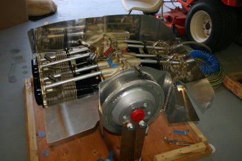 |
| The rear baffles need quite a bit of work. The instruction suggest removing the oil drain, dip stick and governor line but I'll hold fire until I get to that particular baffle (hopefully tomorrow). | 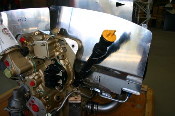 |
| The instructions start with the side baffles, the LHS has two parts which attach directly to the cylinders. The clearance was very tight and the rocker covers prevented the seating of the baffle parts. | 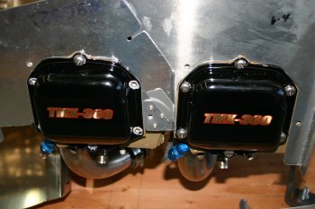 |
| After various struggling, I decided to remove the rocker covers to help work out the needed profiles.
The rest of the afternoon was spent shaping, match drilling the strengthening tabs and trimming as needed. | 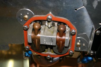 |
| The end result for the LHS baffles. | 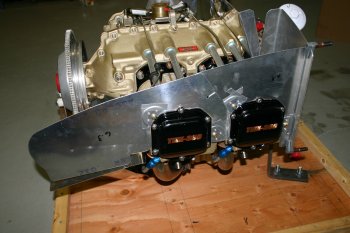 |
| The result for the rear RHS baffles. | 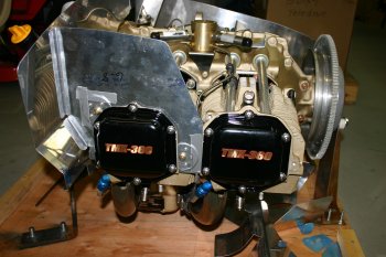 |
Fri 02 September 2005 | |
| Continuing with the baffles - the upper rear mount uses the engine crankcase bolts - more taking my finished engine apart! | 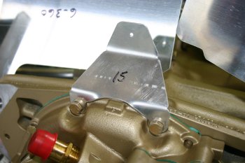 |
| The LHS rear baffle has a strange alignment. The plane that the bolt location is in is well aft (1/2") of the part 15 brace mount. Not quite sure of the process, may need to put a bend in. Some trimming needed but pretty good out of the box. | 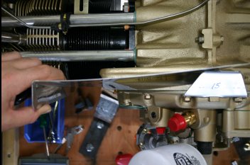 |
| The RHS rear baffle on the other hand, needs significant trimming and working. The good news is the plane of alignment between the rear surface and the #15 brace seems much better. | 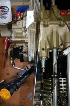 |
| Lots of trimming by file, rotor burr and scotch brite wheel. Not difficult just taking it slowly and carefully to try and reduce any excessive trimming. | 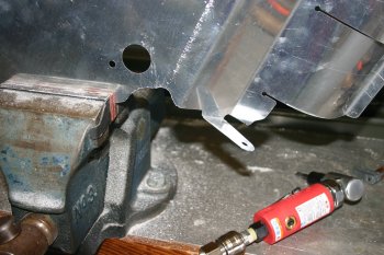 |
| Photo of the front looking back on the RHS rear baffle. | 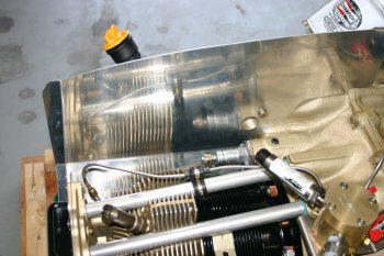 |
| The problem with the RHS rear baffle to RHS aft cylinder baffle (parts #7 & #8) is the gap. Not sure of the 'best' solution - looking at some of the other guys websites, cutting the flange off and using a piece of AL angle. More thought needed and probably no decisions until the engine is on the aircraft and a lower cowl is roughed in. | 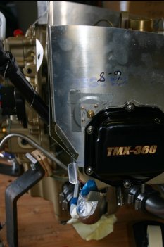 |
| Then onto the front baffles. The LHS uses the cylinder mount point (right of photo, half way up) which provides the top fixing of the angle stiffener. | 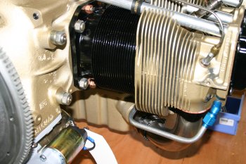 |
| The stiffener is based from a .063 angle, the shaping was fairly easy, just requires time and effort. | 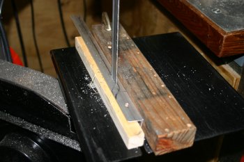 |
| This is the underside of the LHS baffle. Note the part #13 (with the blue plastic on). I didn't understand the original layout - this will get a piece of angle at the top to support the lower surface of the baffle floor. | 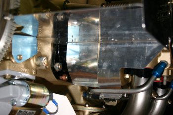 |
| The 'finished' support for the LHS baffle floor. In general so far the baffles haven't been too bad, just slow steady process. | 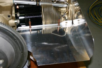 |
Mon 05 September 2005 | |
| I started the morning by drilling the location for the high pressure oil feed. It was close but needed some tweaking. The mistake I made was to cut the 'C' chanel to the inboard direction - a better solution would be to go aftwards. Not sure how I'm going to deal with it yet, I might trim more drastically the thin .032 material and just use the stiffner .063 for the shape / covering. | 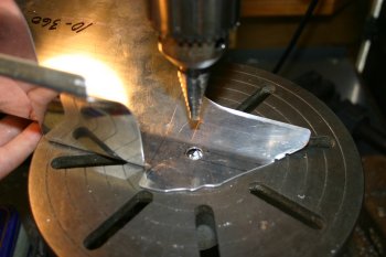 |
| Next I drilled the #14 & #16 parts which provide the vertical support to the two intake floors. This is a BAD way of doing this. The LHS version resulted in a poor edge distance and the RHS is the wrong height due to the stiffener going under the floor pan rather than above. Oh well time for lunch and break! I might have to re-make these parts but I don't hve much .063 stock material. | 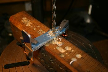 |
| The stiffner was a simple set, clamp and drill. Some bevelling of the trailing edge was needed to help it sit neatly into the locaiton. | 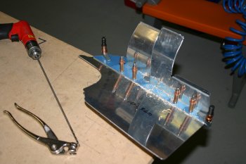 |
| Then I decided re-check yet again the box the baffles came in and screwed up the individual pieces of packing paper. Low and behold I found the missing #9 part. I should know better - the VANs packing is SO good. However I had already checked this box multiple times but it was still there. | 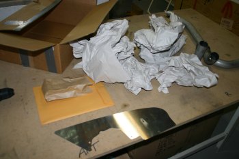 |
| I spent the rest of the day sorting some of the bracing. The LHS rear bracing includes the baffle / oil cooler stiffening and the cross member. The vertical angle was simple - it needed 'rounding' of the vertex to help the fit and some careful drilling where it replaced the spreader washer part. The cross member was slightly harder, it needing careful cutting and a joggle on an angle to step up the .063 thickness of the AL angle. All worked out OK in the end. | 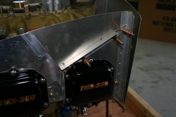 |
| Also sorted the RHS brace which is a piece of simple .040 folded angle. Position and drill. | 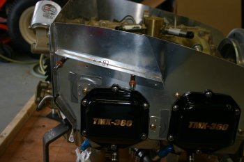 |
Tue 06 September 2005 | |
| A bitty day. I started by remaking the #14 bracket and drilling it all up. | 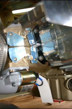 |
| Next I tidied all the bracing rivets. I'm using flush head rivets for all the internal walls wherever possible. Also sorted the #9 strengtheners. | 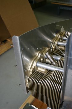 |
| I also fixed the height for the outer rear LHS baffle. This helped with the alignment of the rear inner LHS baffle. | 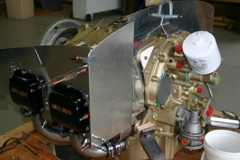 |
| The baffle needed some more trimming, the upper section seems to still need to be at an angle which lead me to.... | 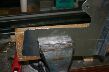 |
| Changing the overall angle. I'll need to create a wedge for this at some point. | 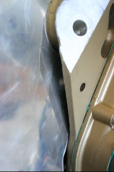 |
Thu 22 September 2005 | |
| Now that the cowls have been fitted (or at least we have a working configuration which may have to be tweaked when we get the prop) I went back to the baffles and started looking at the trimming needed. | 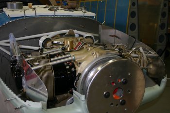 |
| The first thing was to set the inward set on the foreward side baffles. NOTE: This is wrong - the baffle should be outside the cowl inlet. | 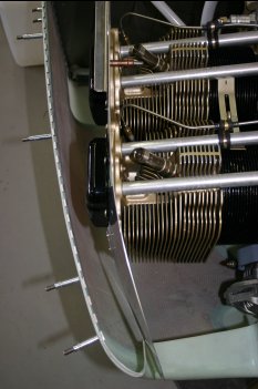 |
| A bending brake and a rough idea of the angle was useful. The 'tricky' bit is the bottom left edge (in this photo) where it is very thin and difficult to get a good even bend. | 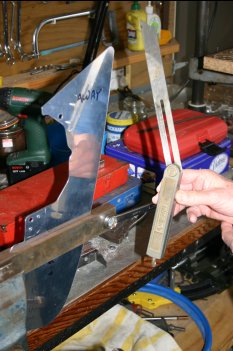 |
| The after photo - again note wrong position of the baffle front edge vs. cowl inlet. Then a small trim at the front and got both sides to fit. Only rough stuff at this point, lots more trimming to go. | 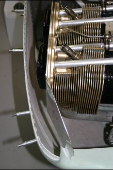 |
| Then I started looking at the trimming of the top line to allow the cowl to sit correctly. After trying to estimate distances, I gave up and mocked up the main side baffles on some card. I just traced the parts out onto the card and then trimmed until they fitted. | 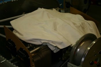 |
| The results - the black is the line for trimming - it looks huge - it is huge amounts of trimming. I started slightly outside the line (being cautious) but ended up back at or even slightly inside the black line. And this is just to get flush with the cowl, another 3/8" needs to be removed to provide clearance for the cowl / engine comparative movement. | 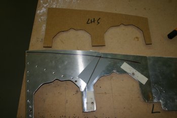 |
| The RHS requires even more trimming as the #1 cylinder is further forward. | 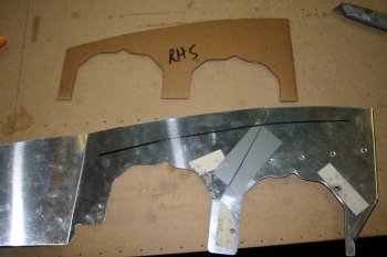 |
| The resulting rear LHS side baffle (the one the oil cooler attaches to). Remember the outboard flange also needs radiusing to match the cowl curves. | 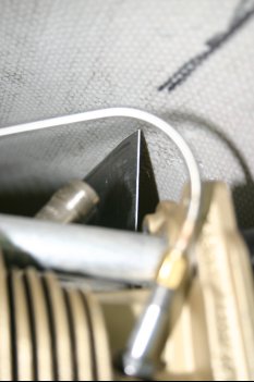 |
| Then onto the forward side baffles. | 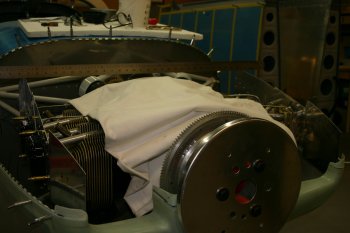 |
| Initial trims give you some idea of the amount being cut off - this is for cowl touching - another chunk to come off yet. | 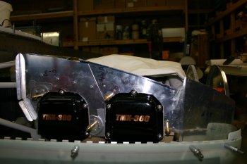 |
| The final rough cut for the day was the forward folded tabs that go into the inlet. More trimming will be needed. I also removed the spinner to ease access for the top cowl. I'm still debating on whether to make a full plenum for the engine - I'm very tempted and it would be another small unique for our plane. My only conerns are: If I was doing it again, I would order the Sam James cowl / plenum kit rather than the VANs cowl - it looks cool and should provide better cooling and more speed. | 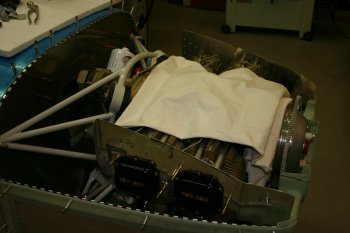 |
Fri 23 September 2005 | |
| I continued all day with the baffle trimming. The main area was the 3 rear pieces. Again I started with cardboard templates and again a good chunk was needed off the top of the baffles. | 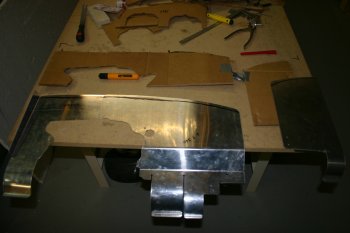 |
| Lots of trimming later - still much more to go (as I found out). The bump in the middle makes things slightly more challenging. | 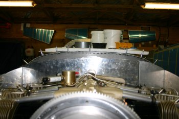 |
| I also found doing one side at a time helped for some of the final work. By the end of the day I had the top / bottom cowls on along with all the baffles in place. The next step is to trim / mark for the 3/8 spacing to the cowl. Also noted was the lack of space between the fuel divider and the cowl material - more investigation needed. | 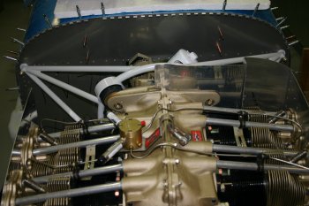 |
Sat 24 September 2005 | |
| Another day on the baffles.... This is the rear baffle. | 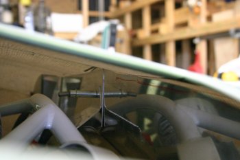 |
| The front RHS looking back over #2 & #4 cylinder. | 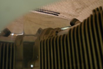 |
| The front LHS looking over #1 & #3. | 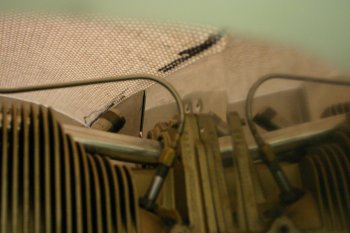 |
| Then we moved onto the baffle / cowl gap, this is meant to be between 3/8" and 1/2" - as I'm seriously thinking about a plenum so want as much height as I can get.. | 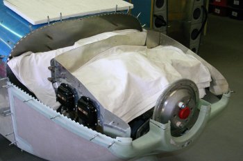 |
| A local pottery club had a source of fine grain clay. | 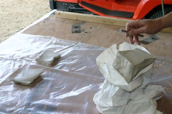 |
| It is sort of similar to putty to work with and I put a bead of clay along the top of the baffles. | 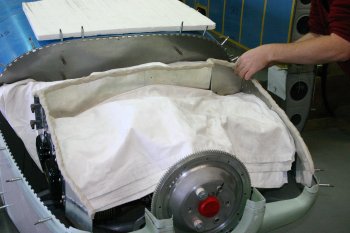 |
| Then the upper cowl was fixed into place and pressed firmly down. | 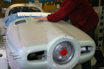 |
| That provided the shape of the cowl, but it was difficult to provide a shape line due to the 'width' of the clay. | 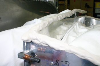 |
| Therefore this was trimmed along one edge. | 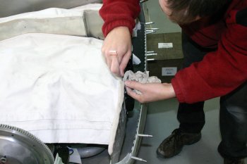 |
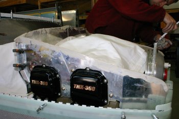 | |
| It was then easy to mark a pre-set distance down around all of the baffle. | 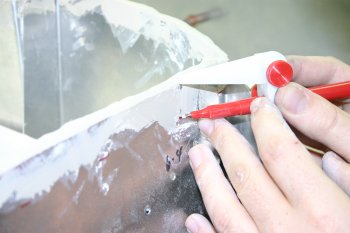 |
| Remove all the clay, wash and dry | 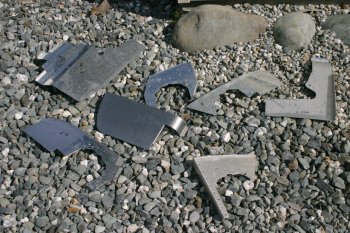 |
| A Dad worked around the edges with a 'flexi-curve' to produce a reference line which should have 3/8" clearance all round. | 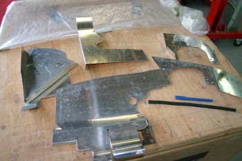 |
| The LHS floor baffle, needs bending and trimming, I used the cardboard template method again. | 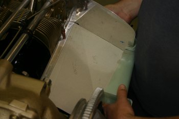 |
| More trimming and bending. | 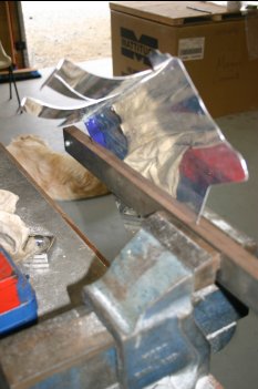 |
| The resulting baffle part looks good, although it will probably need more of a downward bend, more refinement can be completed as needed. | 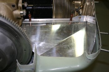 |
Sun 25 September 2005 | |
| Today was a short day in the shed. I did some minor trimming on the LHS baffle floor | 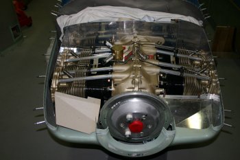 |
| And a cardboard template and first trim of the RHS floor. The next step is to sort the bend line. | 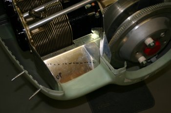 |
Mon 26 September 2005 | |
| Today was spent with the baffles again. The bend in the RHS floor baffle was simple enough although I'm not sure the amount was right yet. | 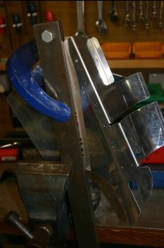 |
| One mistake I made with the baffles earlier was the "C" cut for the oil pressure line. I cut it towards the inboard corner - what I should have done is go aftward. I ended up removing a larger area of the floor (the black marked area) and keying the 1/8" stiffener in the right direction. | 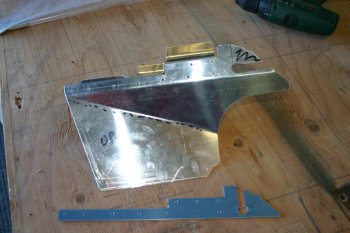 |
| Slowly getting there, lots of try, mark, trim & repeat. | 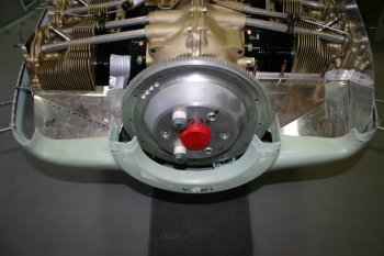 |
| The RHS bracket (part #16 I think) needed to be remade - after recovering some .063 it was just a mark, trim test etc.... | 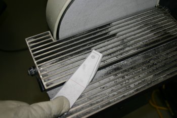 |
| We also increased the downward bend on the LHS. | 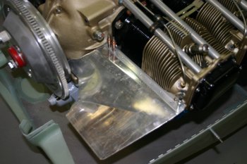 |
| This was the RHS result of the bracket and some temporary fastners. | 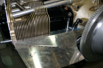 |
| I also trimmed much of the excess material creating the needed 3/8" space between the cowl and baffle tops. | 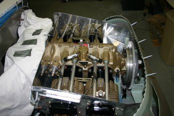 |
Tue 27 September 2005 | |
| Both the baffle floors needed more bending / shaping. Slow iterative process. | 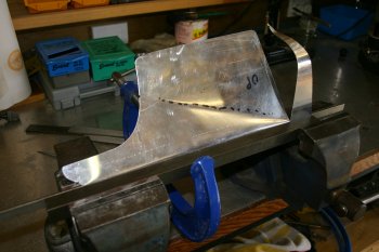 |
| The challenge was not to distort the shape too much - particually where the material was very thin - like the inboard edge of the RHS floor baffle after my (wrong) C cut. Two pieces of stock steel between two large vices seemed to work quite well. | 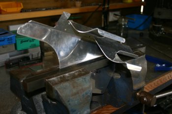 |
| One problem that I can see coming is the spark plug lead on the #2 cylinder if we want to use an angle on the baffle sides for a plenum. More thought needed, I really like the idea of a plenum but it is these kind of complications that might make it hard work. | 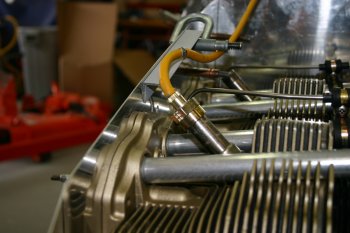 |
| Next on the list is the front baffle - this has a number of independant areas, the floors and the 'upper level'. A cardboard template gave a good starting point. | 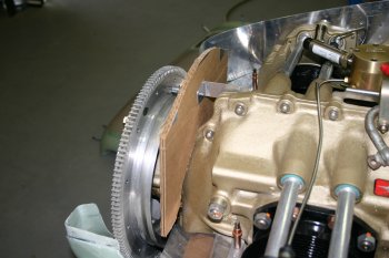 |
| This shows the clearance is fine in the middle, but the edges of the centre section of any plenum is going to need some profiling to get round the fuel divider. The current plan is to use a 90 degree elbow to assist with some of this problem. I think overall I'm coming down on the side of the extra work / complications of a plenum, with the escape clause that I'll try and use as much of the standard VANs baffling as possible which means I can always revert to fabric seal if needed. | 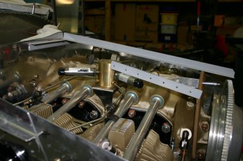 |
Wed 28 September 2005 | |
| Then more trimming / testing / fitting for the floors and side baffles. | 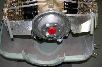 |
| The side to floor fixing is done by a single piece of AL angle on the LHS and two pieces on the RHS. The LHS (Part 2S) is slightly easier to start with but rather intricate bends / joggles and filing. Slow careful work. |  |
| The resulting piece cleco'd to the floor | 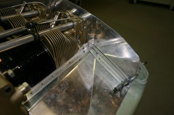 |
| A close up on the interesting bends (Part 2, 2R & 2S). | 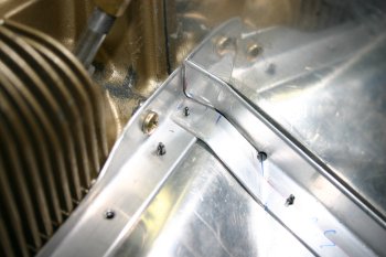 |
Thu 29 September 2005 | |
| Half day today, starting with a refinement of the cowl / baffle gap. A bit more of the clay method - works really well. |  |
| Dad then went onto the oil cooler location / cut out. |  |
| As an experiment for future requirements, we tried using the milling drill for a rectangular hole. Starting with precision corners. |  |
| And then using a router cutting bit and moving the work on the screw threads. |  |
| The end result - works quite well, the direction of the cut and lots of lubrication are needed to get a clean edge. The lower edge of the cooler is about 3/4" lower than the top of the #4 cylinder. |  |
| The top of the cooler mount will need a bit of trimming and we are still debating about adding a .040" spacer between the side and rear baffles. |  |
| I continued working on the baffles and the front RHS baffle angle. The instructions mention a mini angle section 10S but no details of size / shape / direction. I ended up going for a single brace which seemed to work OK - I might still beef up the join on the outside, but I'll review once any plenum structure has been completed. |  |
| The end result after some trimming and drilling. More gap between the cowl and the baffles will be needed but I'll wait until later. I'm also tempted to make a fibreglass smoothing entry duct to help with the transition between the fabric seal and the AL baffles. |  |
Fri 30 September 2005 | |
| Dad continued with the oil cooler mounting. Mainly just match drilling and shaping. Also a .063 spacer was made to go between the side and rear baffles, this helps move the oil cooler slight back away from the cylinder fins. Not sure if it will be needed in the final solution, but easier to make and shape now. |  |
| I continued with the front baffle floors and front surface. Card process again used to get the basic shape for the compound cuts. |  |
| Again quite a significant amount of material was removed, this time I used snips rather than the band saw - worked OK. |  |
| Then I progressed to the F11A tie plate - this is a fiddly little plate which is very difficult to work with as getting clecos in and alignment of the various curved / bent surface is a bit of 'art form'. The instructions have almost been thrown away by this point. |  |
| Dad also marked up the oil cooler for trimming near the engine mount. I then attacked it with the sabre saw and rotor burr. |  |
| The other braket I worked on was the front crankcase bracket for the LHS floor baffle. Fairly simple, just shaping and trimming. |  |
Sat 01 October 2005 | |
| Another day - and guess what - more baffles! Geez these take FOREVER! Dad continued with the oil cooler mounting / bracing. We are trying to keep all the surfaces nice and smooth to help provide better cooling. | 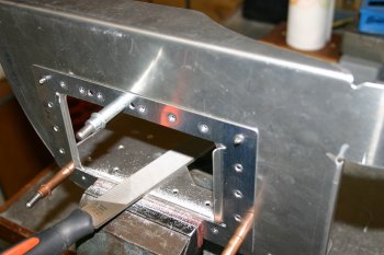 |
| He also sorted the dimpling and fixing of the rear baffle to the oil cooler. Becareful sorting out which way all the dimples go...... ;-) | 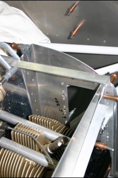 |
| I continued with the front baffles, the LHS baffle is a problem in that we can't get the recommended F1A plate in on the front surface. There is no (/ not enough) material on the baffle floor (shown between the centre baffle and the ring gear). | 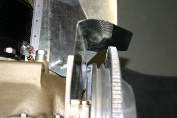 |
| I decided to finish and lock the position of the RHS front baffle first by making a small angle fix for the front section. The plans use a F11B plate but that has some funky angles that I didn't really want to play with, so this seemed like a simpler solution and the pro-seal can seal the gaps. | 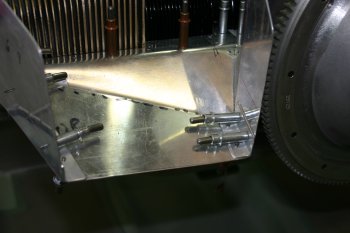 |
| Back to the LHS, I made a 120 ish degree bend in a plate and then focused on getting the front and floor square with each other and the front in the right plane to meet up with the other side. | 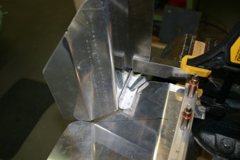 |
| It took a couple of attempts and a remake of the bracket but got there in the end. | 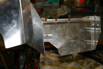 |
| The VANs baffles nearly finished, only the LHS front / LHS floor mini angle to sort (instead of the F1B) and then it is ready for some priming. The next stage (non-standard) is to sort the plenum structure. We have been thinking hard over the past few days and I think we have a cunning plan which should be simple (ish), light and easy for maintenance. The devil as always will be in the detail! | 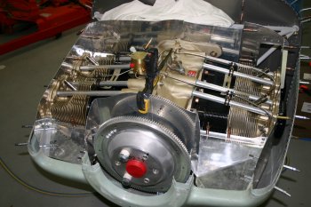 |
Sun 02 October 2005 | |
| The rear right side of the baffles don't work well, so some modification was needed. The main issue was the angled section between the two vertical edges. | 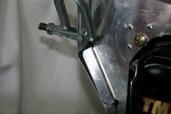 |
| Dad marked and trimmed the RHS baffle (Part 8) and then flattened the remaining material. | 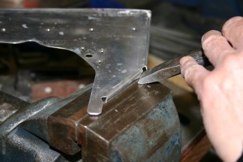 |
| This then provided enough flat material to work the fixing for an extra braket. | 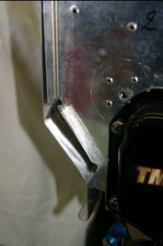 |
| Dad made up a new bracket, drilled and then moved onto prep'ing for spraying | 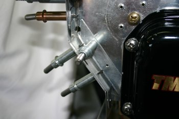 |
| I mean time worked on the front baffles. To start with was the completion of the LHS floor inboard angle. Simple enough, then I went round match drilling everything to #30 and dimpling / countersinking where needed. | 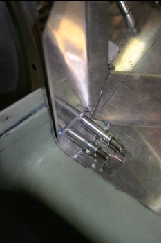 |
| This some of the pile of off-cuts from the baffles. There is a sgnificant amount to be removed - just take it slow and steady, use the cardboard templates to start with and the clay to refine. | 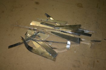 |
| Then with the weather looking good which switched modes to prep'ing parts. We have a large batch of things to prime. | 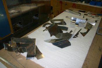 |
| Dad worked through the smaller fiddley parts whilst I did the large sheets. Edging, smoothing and thoroughly scuffing. | 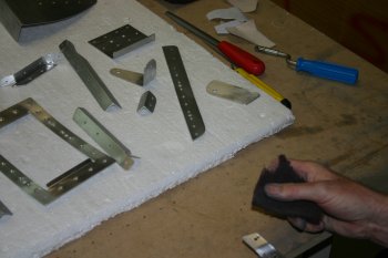 |
| Then it was AllSol degreaser ready for the Acid wash / rinse before priming. The problem was we where about an hour and half too late (all day), the wind came up, the temp went down and we had to flag it. We will continue to amass parts and hopefully the weather gods will oblige later in the week, like most things it is the preparation which takes 90% of the time. | 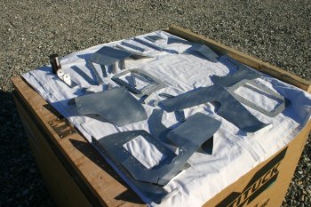 |
Fri 07 October 2005 | |
| The baffles cleco'd together - this is the view from the rear looking forward. I have a whole range of photos of the various parts if needed - let me know. | 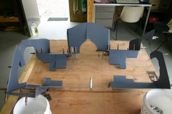 |
Sat 08 October 2005 | |
| Today it was 'black death' day (Pro-seal). We decided to use a layer of pro-seal between each of the baffle surfaces and parts. This is probably overkill but it should help with the vibrations and will provide an air seal for the joints. | 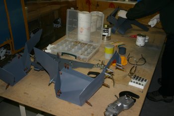 |
| We worked around all the reinforcement brackets and then moved to the real oil cooler baffle. That took the majority of the morning, most of the rivets were fine, one or two might need a little re-work but we can wait for the pro-seal to set first. | 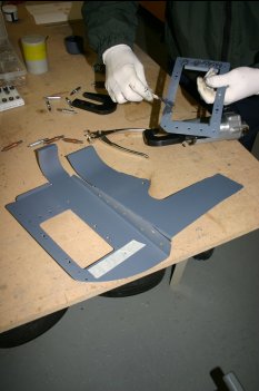 |
| After lunch we went on with the forward baffles. The floor and side baffles need some careful sequencing to ensure that you can get rivet gun / squeezer / back riveting / bucking bars in. One non-standard thing we did was to use flush head (AN426) on all the internal surfaces. This has the obvious benefit to help keep a smooth surface for less turbulence inside the plenum but it also makes riveting simpler as the raised AN470 heads are harder to work with the bucking bar / back riveting plate. | 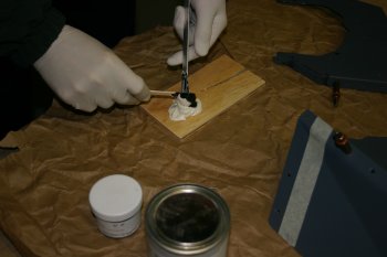 |
| The resulting 4 corners of the baffles. Not sure yet how we get them on the engine - but I'll trust that it is possible. A fairly long day and not a huge amount to show for it - however I'm pleased with the results and the our clothes survied the process. I'm still not sure about the finishing of pro-seal joints. | 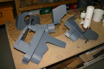 |
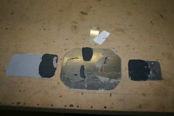
| I also sorted a test case with pro-seal, using three surfaces - one primed, one ALCLAD and one coated with boelube. This is testing for a good release agent for the custom access panels for the front upper deck skin. | 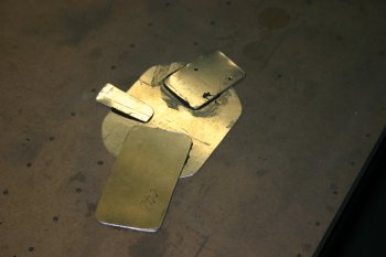 |
Mon 10 October 2005 | |
First up was the results of the Pro-seal experiment.
|  |
| The rest of the day was spent on the baffles - again. I cleaned up some of the holes from the ProSeal and fitted to the engine. I knew the front baffles weren't trimmed so that was the next step. With the starter gear wheel removed, getting to the upper cowl surface was a little easier and a 'first-cut' line was made. | 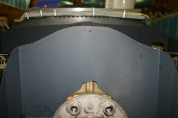 |
| After lots of trimming, I got the contour pretty close to the cowl shape, then it was more, mark 1/8", sand, re-fit. Each time, the lower and upper cowl had to be removed / fitted - slow, repetitive process. | 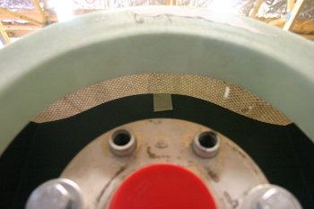 |
| By the end of the day everything fitted - still a little more trimming to get the 3/8" clearance but the plenum is the next task. Once that is done then the final trimming can be started. More research and thinking time on the top cover, debating between fibreglass or AL top, he fuel divider is also quite tight. | 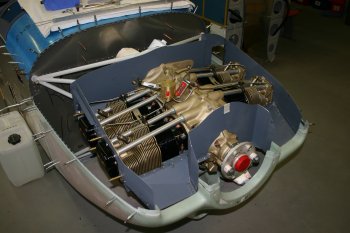 |
Tue 11 October 2005 | |
| Dad worked on the additional wedge to support the rear LHS baffle. The angle of the baffle sheet doesn't match the engine location. We tried a simple tube spacer, but I think something with more spreading of the load is a good idea. This is a piece of 1/2" / 3/4" stock. | 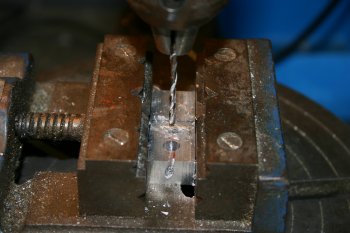 |
| This the shaping before hand. | 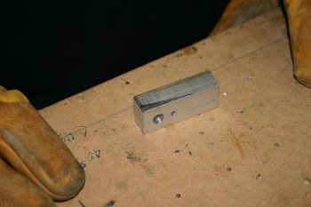 |
| The final result - works well - and the keeper rivet will hold it all in place. | 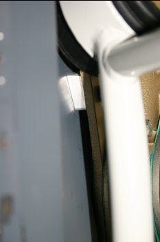 |
| Dad also started work on an additional baffle which will go above the oil cooler inlet. This will also provide a single run for the rear edge of the plenum. | 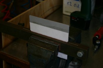 |
Wed 12 October 2005 | |
| Dad continued with the test run for the baffle filler. By this point we had worked out the stress relief holes were in the wrong location. The distance from the bend line to the resulting outside surface is 3/32". | 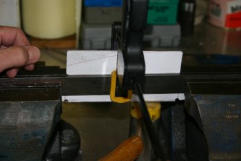 |
| The alignment of the front surface is based from the rear inboard baffle. | 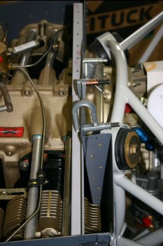 |
| The first attempt - pretty close, a bit short of material on the aft attach plate. | 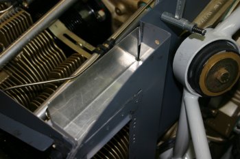 |
| A quick modification of the CAD layout - and try again. | 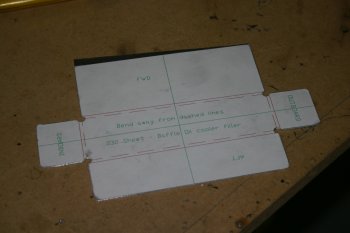 |
| This time everything fitted much better. The upper 4 AD4 rivets that hold the oil cooler bracket also now go through to this mini-baffle. The lower surface is in line with the top of the oil cooler entry and the front surface is in alignment with the rear baffle that is further inboard. | 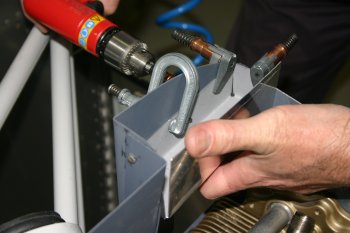 |
Fri 14 October 2005 | |
| First up Dad sorted the mounting for the mini-baffle over the oil-cooler inlet. This is now fixed so the forward face can be used for the plenum side plate mounting. | 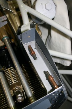 |
Mon 27 November 2006 | |
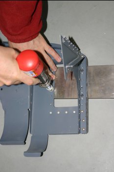 | |
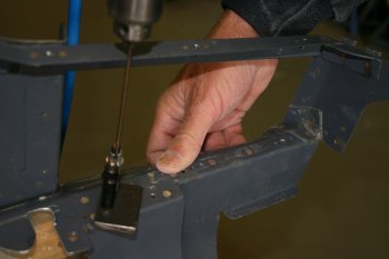 | |
Wed 13 December 2006 | |
| These are the baffle penetrations - they are a two part design (which isn't obvious from the catalogue photos) but the large hole size is 3/4" and the spark plug nuts are 1" - a modification to a plan is needed. | 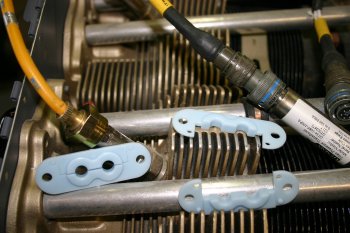 |
Thu 14 December 2006 | |
| This is the current thinking / possible option for the baffle penetrations - gang up multiple plates together and make a bigger hole in the middle. A quick bit of CAD work. | 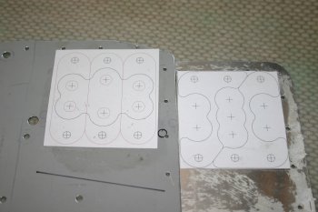 |
| And some scrap AL sheet. Seems to work OK, although I need to modify my drawings slightly. | 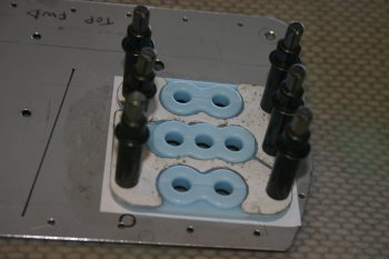 |
| This is the other side - I should be able to get the 1" connectors thought the gap ;-) | 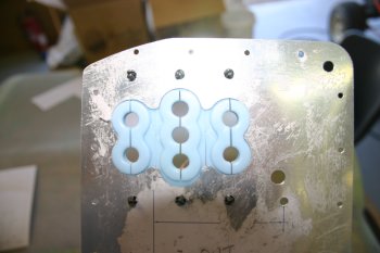 |
Sat 20 January 2007 | |
 | |
Thu 01 March 2007 | |
| Prep'ing and cleaning of the baffle parts - then out to dry. | 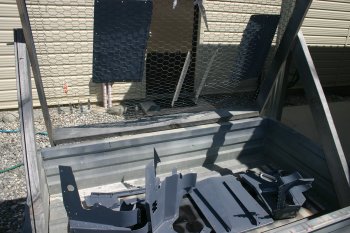 |
| Then moved inside for drying over night. | 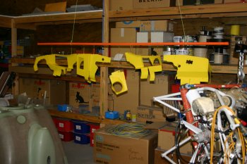 |
Sun 11 March 2007 | |
 | |
Sun 08 April 2007 | |
 | |
Fri 27 April 2007 | |
| Also went back to the lower baffle ties - still not really happy with the solution, but will probably end up with the simple safety wire option - do need to get some .040 for it though. | 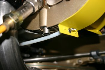 |
Wed 30 May 2007 | |
| Then back to the baffles - this is the new plan / solution. The safety wire goes through a #4 stainless steel washer and then round fishing split ring and back trhough the washer. This provides a round surface for wire to bear against and the washer will hopefully prevent wear. | 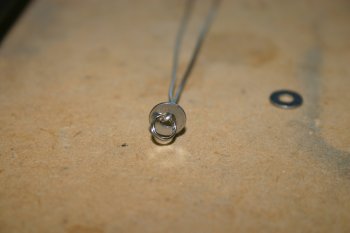 |
| The installed version, the front was pulled up and then twisted to reduce the bulk of the remaining play. | 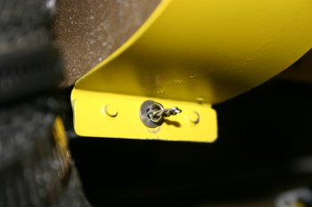 |
| Home | Carl Morgan | Previous|Next|Latest |