


 |
 |
 |
| Home | Research | Delivery | Empennage | Wings | Fuselage | Finish | Engine | Electrical | GRTDecode | Previous|Next|Latest |
| Fuselage | Cockpit | Fuel Systems | Undercarriage | Canopy | Flaps | |
Cockpit | |
Sat 24 January 2004 | |
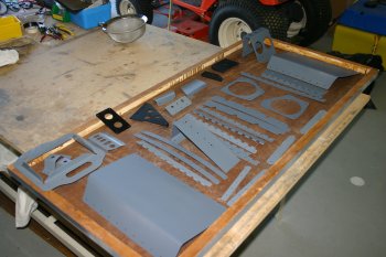
| Moving onto something a bit different, I got the seat components out and started laying out the parts to understand what fitted where. Also sorted the upper seat hinge piano, although the seat side of the hinge looks a little small. | 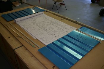 |
Mon 26 January 2004 | |
| The upper piano hinge across the back of the seats is only 15 1/2 " long by default (as per plans) but this means the edge distance is very marginal for drilling the end rivets. As I have some extra P3 piano hinge so I decided to make a longer replacements. If I had known I could of just cut the 3' P3 stock that was supplied in half and I would have had sufficient to do the same for both sides. | 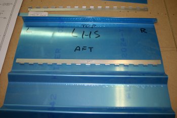 |
| The after version. Much happier with this - a trivial thing but it would of annoyed me otherwise. | 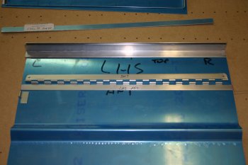 |
| I then cut the uprights and cross members from the angle stock. The seats are going to be very rigid with the angle framing. | 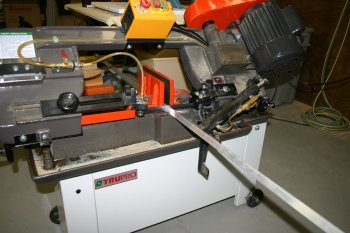 |
| Dad sorted the lightening holes and tidied the edges of the rear seat brace. | 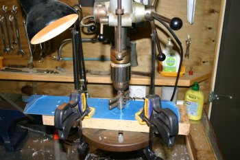 |
| We then clamped and drilled the lower corner locations for the seats. For the rest of the rivets we will wait for the Avery order to show up, which includes a rivet fan. | 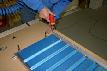 |
| Dad finished the angle corners and smoothing whilst I was preparing for the even social. Early finish and out to see the locals. | 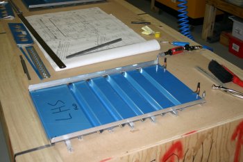 |
Tue 27 January 2004 | |
| To start the day I did some clean up of some of the panel sub-structure. Filling a bit of time whilst we waited for the Avery FedEx order to arrive. | 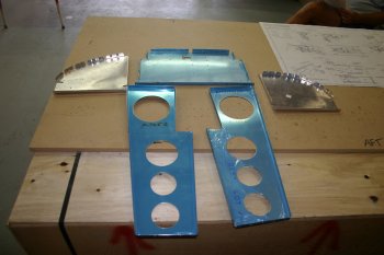 |
| The FedEx order with the rivet fan arrived mid-morning so I spent the rest of the day doing the seats. Firstly I continued to layout and setup the edge angles. | 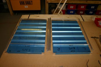 |
| I set up a drill jig with the 5/16" distance and then started working through the drilling. All holes were completed at #40 and then later enlarged to #30s. | 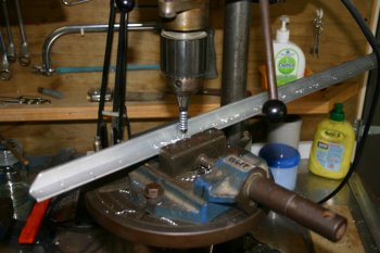 |
| Clamping the side angle is a little difficult as all the normal cleco methods don't have enough 'depth'. I ended up using old fashioned clamps. I took a bit of time over the line up and spacing checks as this is a more 'visible' part of the aircraft finish. | 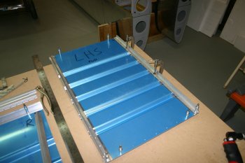 |
| Once most of the #40 holes were drilled and the alignments checked then it was easy to enlarge to #30s. | 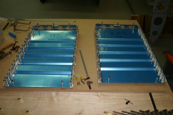 |
| Then finished the day by deburing and cleaning up the parts. Pretty much ready for priming although I still need to sort the upper and lower piano hinges. Hopefully complete it all tomorrow. | 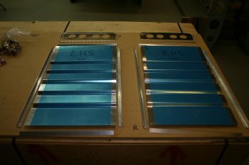 |
Wed 28 January 2004 | |
| I spent the day continuing with the seat backs. They look pretty simple but with no pre-punched holes and being fairly visible I took my time marking up and drilling. The rivet fan (received yesterday from Avery) makes things a little easier. | 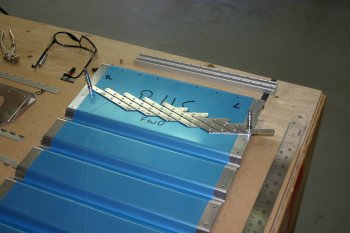 |
| After centering the upper piano hingeand cleco'ing, the other holes were easy to sort. Everything is being drilled as #40 at this point. | 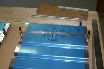 |
| The vertical angle down the left and right sides of the seats has to be rebated for one side of the floor piano hinge. I went a bit high tech (probably more so than needed) and used a rotary burr and a cross slide in the pillar drill to end up with nice neat, square rebates. Took a bit of extra time, but pleased with the results. | 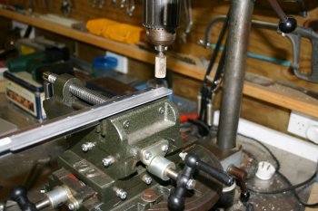 |
| The fully drilled seat backs, with hinge mounts attached. Next stage is to drill out to #30 on the remaining cross members. | 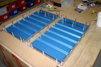 |
| The end view of the lower left corner of the left hand side seat. You can see the interface between the angle, skin and hinge. |  |
| A shot of the seats cleco'd together laid out in the plane. A 20 minute distraction at the end of the day, and No I didn't sit in it and make aeroplane noises (I'll wait for things to be riveted together first....) | 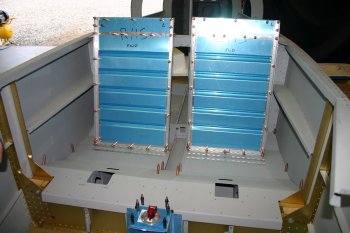 |
Thu 29 January 2004 | |
| I started the day finishing of the deburing and cleaning up the seat components. | 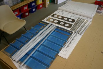 |
| The bits were then added to the pile for priming. This is getting quite large now, it includes all the empennage plus other prep'd parts.
Basically I'm still undecided on the 'best' method of priming. The options range from doing it all our selves to using the local professionals that I am interested in doing the final external paint job. Or something in between, lots of options, all of them cost money. We are starting to get to a point where I will need to make a decision so that we can progress. | 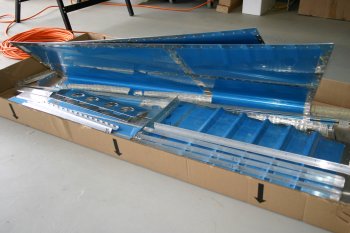 |
Tue 10 February 2004 | |
| The panel substructure doesn't really need to be done just yet, however we would like to try priming these part and see how it goes. We are also considering our options for within the cockpit space and are looking seriously at Anodising as a finishing option. | 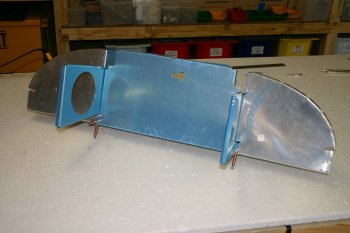 |
Thu 12 February 2004 | |
| Whilst the wind was roaring I started to look at the rudder pedal components. As the aircraft will be flyable from the left or right seat we have the dual brake system option. | 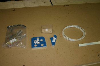 |
| I cleco'd the 4 rudder parts together and carefully cleaned up the edges on the sander and scotchbrite pads. Our intention at this point is to use hard anodising for these surfaces so I'm being careful to keep them scratch free as much as possible. | 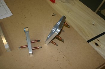 |
| I also cut the 8x 4" angle stiffeners. The kit ships with 1x 9" piece of angle, plus the 2x 9" pieces in the dual brake kit. The remaining 9" I took from the 3/4 X 3/4 stock that I had left over from the seat cross braces. I hope I don't need to keep that length for anything else. | 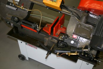 |
Sat 28 February 2004 | |
| We continued with the rudder assemble today. Dad focused on the mounting and I continued with the pedals. | 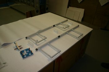 |
| First thing for me was to re-trim the 8 angle supports for the pedals. | 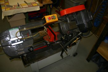 |
| The brake side plate needed some more edge clean up work, but with the radius of the corner being quite tight an improvised sanding tool was needed. | 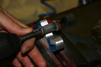 |
| Dad worked on the drilling of the plastic blocks. Note the end blocks are handed, the rudder tube is drilled in at a slight angle. | 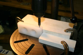 |
| The rough setup. Dad then moved onto the support bracket. | 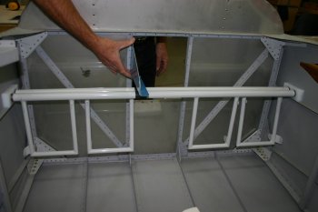 |
| We decided no to trim the support at all and provide the maximum flexibility for rudder adjustment, although I doubt we will need very much movement. A notch has to be cut for the firewall angle. | 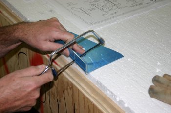 |
| Sabre saw for the longer cut and then some further trimming and filing. | 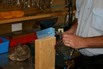 |
| I moved on to drilling the angle supports. I elected to pilot drill the lowest holes on both the aft and sides of the angle supports via a jig to give an repeatable and accurate hole. These were then opened to #30's for the pre-punched rudder pedals. | 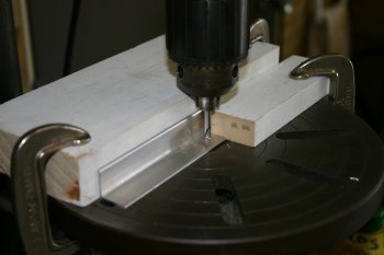 |
| Using the drilled locations the angle was clamped and the rest of the holes could be completed. Careful support for the angle (with the radiused internal corner) was needed. | 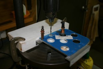 |
| The parts starting to look like pedals. I then marked up the trimming for the 'non-master cylinder' side angles. | 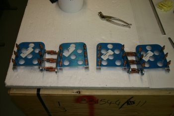 |
| I did the trimming in a two stage process, starting with a rough cut with the hand held rotary burr. | 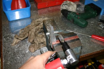 |
| And finishing with a burr in the pillar drill plus a 2 axis vice. I made a wooden wedge to set the angle for the final line. These can then be smoothed and finished. To be continued tomorrow. | 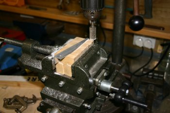 |
Sun 29 February 2004 | |
| Dad continued working on the rudder support bracket. The rotary burr in the pillar drill again. | 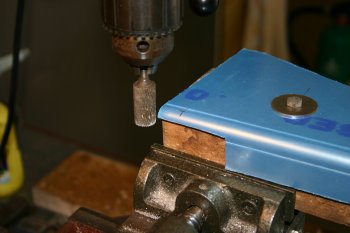 |
| The vertical flange needs drilling for the firewall stiffener. | 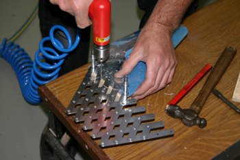 |
| And rather than trimming the support we decided to just put the lightening holes in instead. Hole saw made a racket but worked fine. |  |
| The final step was to clean and debur all the edges and smooth with the scotchbrite wheel. | 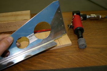 |
| Meanwhile I continued with the rudder pedals. After remaking one of the angle supports that I damaged yesterday during the rotary burr work I moved onto the main and the side plates countersinking. | 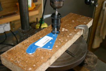 |
| Then it was the normal shaping, filing, smoothing and scotchbriting. I also did the angle shaping at the base of the supports. | 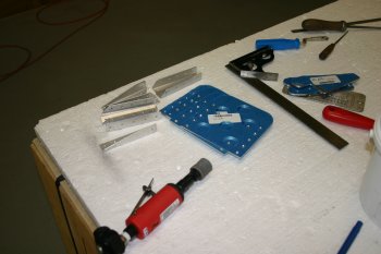 |
| VANs have a very specific call out for 3/16" drills (as oppose to #12's which are normally used for AN3 bolts) so I did as the instruction said. I opened the pivot points on the pedal side brackets and the powder coated swinging rudder controls. | 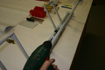 |
| The problem was the 3/16" drill was too "accurate" and didn't provide enough clearance for the bolts. But it was VERY close so I ran a 3/16" reamer through by hand. | 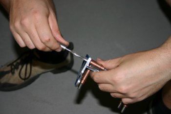 |
| I then located and organised all the bolts need and put the whole assembly together. The pedals are a very tight fit and the -10L washers are going to be a 'challenge'. | 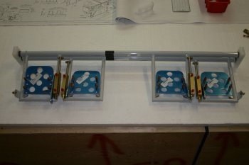 |
| The next step is the drilling of the brake master cylinders to pedal horn. I'll sort out a good way of centering everything first. More research needed. | 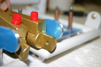 |
Mon 01 March 2004 | |
| I started by sorting the brake horn drilling for the rudder pedals. After reviewing the instructions on Dan C site the solution was obvious (follow Dan's advice!). I hung the rudder pedal tubes on a couple of blocks and lined everything up. | 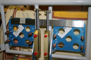 |
| Then using a small pilot drill scribed an arc on the plastic sheet. | 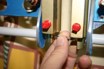 |
| Then it was easy to locate the centre of the 'lump' and find the intersection. As the pedal configuration is duplicated (eg P1 left and P2 left) I decided to match drill both horns at the same time. This was a mistake (see below), if you have dual brakes, mark the arc independently and treat each pedal separately. | 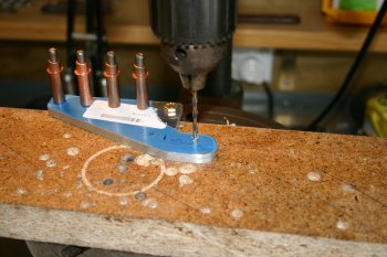 |
| The P1 (left seat) pedals. All nicely aligned and looks great. | 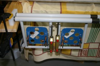 |
| The P2 (right seat) pedals, difficult to tell from the photo, but the pedals are at different angles at rest. Probably not a big thing from a flying perspective, but annoying never the less. I tried swapping the pedals / brake cylinders around but the error comes from the weldment being slight different P1 vs P2. One of the occassions to forget about the minor problem / mistake and move on. | 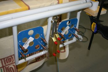 |
| As we plan to have the rudder pedal assemblies hard anodised I decided to take a bit of extra care with the surface finishing of the pedal cut outs. This is the sort of decision which is quick but the resultant work is multiple hours. First I had to find something that could be used to sand away an 1" hole, which took another 30 mins. |  |
| We ended up dressing down the ScotchBrite wheel down to about 15/16" and then taping medium grit paper to it. The result is a really nicely finished internal surface. Worth the extra time and effort. | 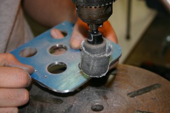 |
| All the rudder pedal parts ready to be sent off for anodising. Email's to be sent tonight, hopefully be able to get them done within a week or two. | 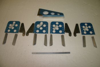 |
Thu 04 March 2004 | |
| The rest of the day I spent preparing the rudder pedals for Anodising. It may seem a little extreme to spend 6 hours on the finishing of this parts but once they have been processed the surface will be like rock and no further modifications are going to be easy. The primary method was a large steel bed with wet & dry sandpaper, finishing with scotchbrite pads. | 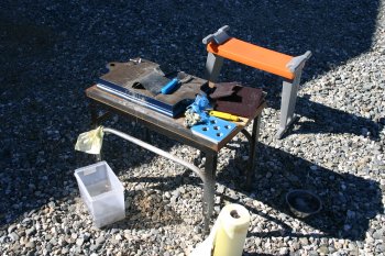 |
| These were then de-greased, and acid etched to give a really consistent non-scratched finish. Took a longish time, but really pleased with the results. | 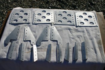 |
| Close up of the satin finish on the front of the rudder pedals. | 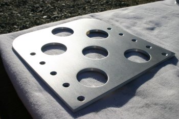 |
| The rudder pedals were then carefully wrapped and boxed ready for shipping to Auckland for processing. Need to contact the company tomorrow before posting. | 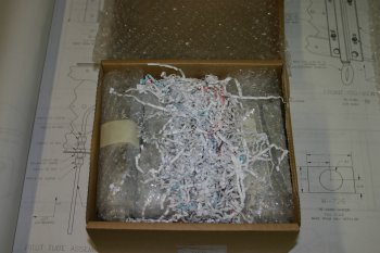 |
Tue 09 March 2004 | |
| I spent the day working on the control column systems. It all looks simple on the drawings but lots of little 'things' have to be completed. | 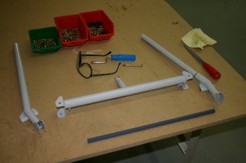 |
| For example the brass bushings need reducing (squarely), reaming out and finishing. This took a good couple of hours. | 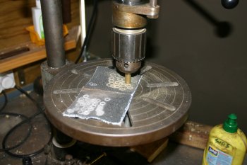 |
| Located most of the hardware components and assembled the structure without many issues, all now flows and rotates freely. | 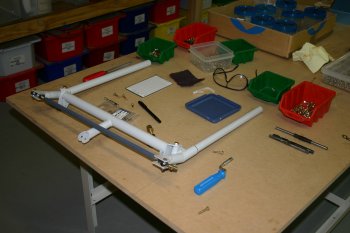 |
| Finally set it up in the fuse, only make up nuts at the moment, but all looks fine. The control sticks are VERY long, I know others have trimmed them and I may do likewise after seeing how much space we have (or don't have). | 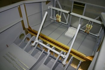 |
Thu 11 March 2004 | |
| Once the wind calmed a little and started the normal scuff, clean and etc process for the left hand side seat. | 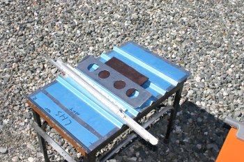 |
| Then I primed it using the spray gun and the result was really good and even. I'll let it cure overnight, hopefully we'll be able to sort the priming of the right hand seat tomorrow (weather dependant). | 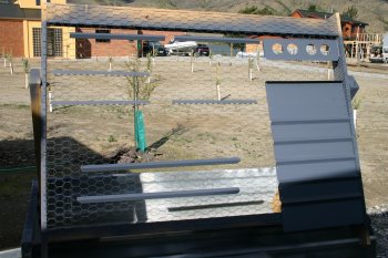 |
Fri 12 March 2004 | |
| First up I prep'd the right hand seat. Normal, scuff, clean, etch then ready for painting. | 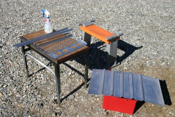 |
| The spray gun process gets easier with practice. I was pleased with the final results. | 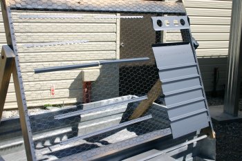 |
Sat 13 March 2004 | |
| As both the seats were cured nicely by mid afternoon - I proceeded to riveted them together. Didn't take long and another finished assembly ready for (touch up priming) and top coat painting. | 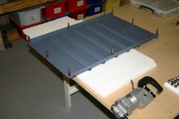 |
| The upper piano hinge rivets are out of reach for the yokes so I'll use the C-frame, but it is easy with two people so I'll wait until Dad is back tomorrow. | 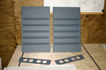 |
Mon 15 March 2004 | |
| I then went back to more part fabrication. The CAD drawings are working well. | 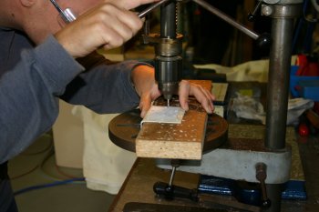 |
| I then had a quick go at making the cut out for the canopy latch in the scrap fuselage. The basic marking up is done with a template from VANs. | 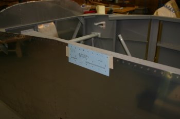 |
| I then made a row of #30 holes and then joined them up with a needle file and smoothed the upper & lower cuts. | 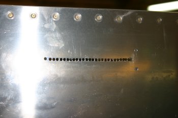 |
| The result (although quick and crude) looks OK, so I think I have a plan of action for the real thing. | 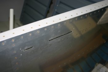 |
Tue 16 March 2004 | |
| We took 20 mins out this afternoon to finish the seats with the C-Frame. End result looks good. I'm trying to see a local upholstery guy about the cushions over the next week. | 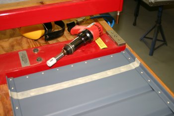 |
Fri 19 March 2004 | |
| Dad spent the morning sorting some of the misc brackets for the cockpit. The Z section in the centre is a neat solution to the problem and very strong. |  |
| Combination of band saw, filing and normal finishing methods. |  |
Sat 20 March 2004 | |
| Dad continued with the Z brackets for the elevator push rod cover. | 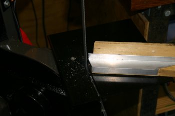 |
| The top sheet was template drilled ready for match drilling with the new fuselage. | 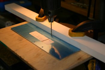 |
| I continued with the seat back supports, these shims and angle form a slot for the rear of the seat. | 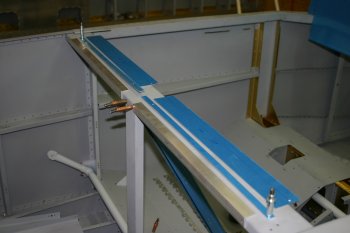 |
| Most of the parts are match drilled to the rear cockpit brace, however the AL angle is drilled from stock. Rivet fan was the easy option. | 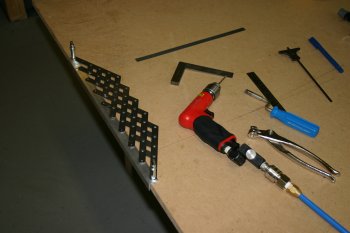 |
| The channel requires another 100 degree cut. I ended up using some wood as an internal support for the bandsaw which helped significantly. | 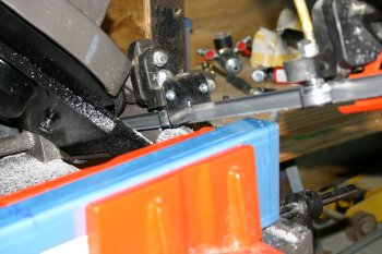 |
| Some of the parts that we have been making over the past few days. Doesn't look like that much but all in all reasonable progress. Evening out with UK visitors. |  |
Wed 24 March 2004 | |
 | |
 | |
 | |
 | |
Sat 27 March 2004 | |
 | |
 | |
 | |
 | |
 | |
 | |
 | |
 | |
 | |
Sun 28 March 2004 | |
 | |
 | |
 | |
 | |
Mon 29 March 2004 | |
 | |
 | |
 | |
 | |
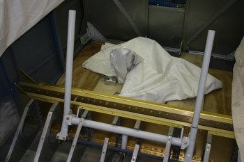 | |
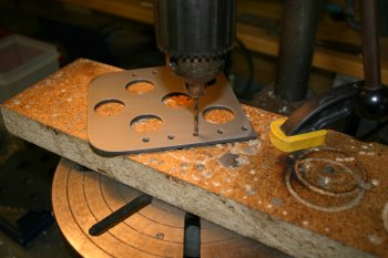
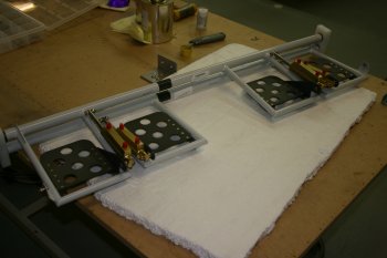
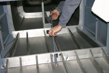
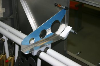
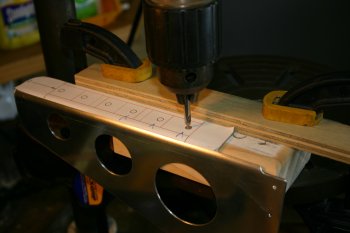
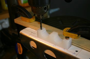
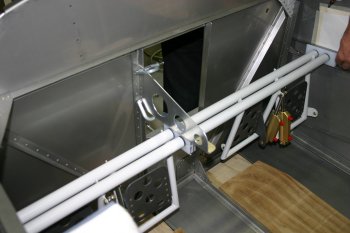
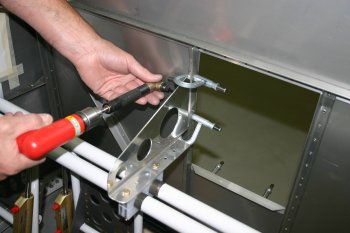
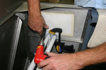
| I made a plate with two 1" holes - 19 1/2" apart - this means the two control columns can be held centered and veritcal. | 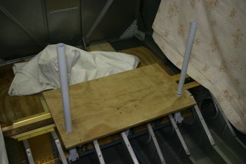 |
Tue 30 March 2004 | |
 | |
 | |
Wed 31 March 2004 | |
 | |
 | |
 | |
 | |
 | |
 | |
 | |
 | |
 | |
 | |
 | |
 | |
 | |
 | |
 | |
 | |
 | |
 | |
Thu 01 April 2004 | |
 | |
Sat 03 April 2004 | |
 | |
Sun 04 April 2004 | |
 | |
 | |
 | |
 | |
 | |
 | |
Tue 06 April 2004 | |
 | |
Fri 10 December 2004 | |
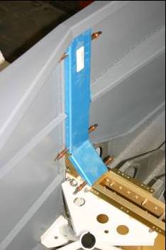 | |
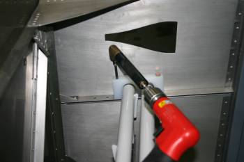 | |
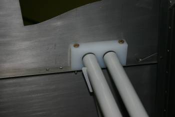 | |
Tue 21 December 2004 | |
| I finished putting together the rudder pedal assembly including castlated nuts / cotter pins. | 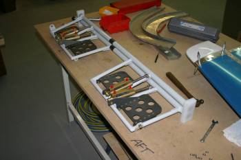 |
| I also sorted the brake line elbows. Locktite 596 was used as a sealant. I also spent some time trying to understand how to sort the parking brake and fuselage forward section. | 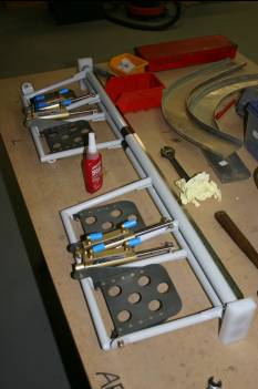 |
Thu 23 December 2004 | |
| Dad sorted the brake line routing for the P1 / P2 link. | 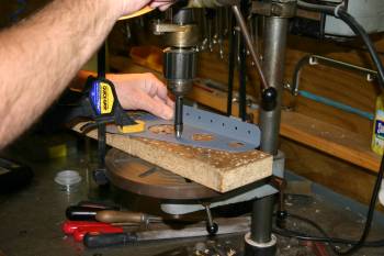 |
Fri 24 December 2004 | |
| I started with the tunnel cover plate. The Z bracket needed some more shaping and the base drilled for the nutplates. | 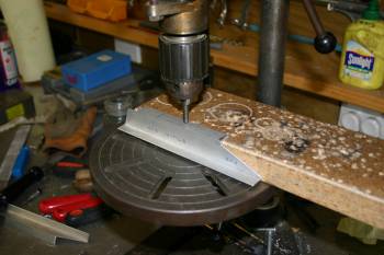 |
| The top plate needs a set for the floor panels. The set angle was just perfect, but it was in the wrong place! | 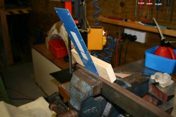 |
| I therefore remade the top plate (and a little larger) and fitted it. Ready for dimpling / counter-sinking. | 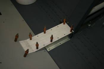 |
| Meanwhile Dad was working on the forward section of the cockpit and the covers. |  |
| Everything gets mounted via a few nutplates. | 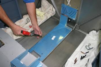 |
| The 'top-hat' for the fuel pump, match drilled. | 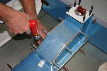 |
Sun 26 December 2004 | |
| Meanwhile I worked on the forward cockpit covers. In particular the airflow pump bracket is basically too big for the gap between the floor stiffeners. I think the problem is actually the floor stiffeners, if you are a slow builder, make sure it is a clean 8" gap between the inside of the angle stiffeners. | 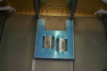 |
| I decided on a slightly different mounting option and removed the flange of the original mount. | 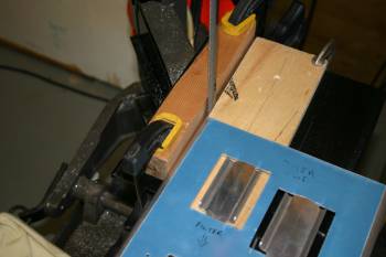 |
| I then trimmed the standard cover by removing the center section. | 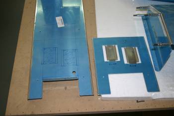 |
| Corner holes and snips were the simplist option. | 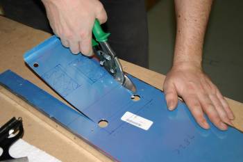 |
| After trimming and shaping, I remounted the parts and match drilled the two parts together. | 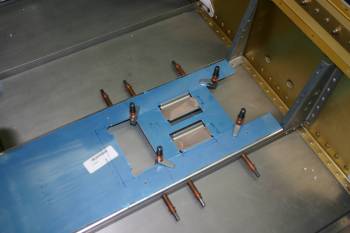 |
| It all came out OK, probably use AD4 426's for the actual mounting, need to prime the parts first. | 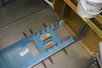 |
Wed 05 January 2005 | |
| I tightened the harness fixtures. These were a problem with the QB fuse and needed redoing. | 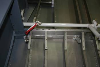 |
| I also removed the control column system and removed some of the binding locations. | 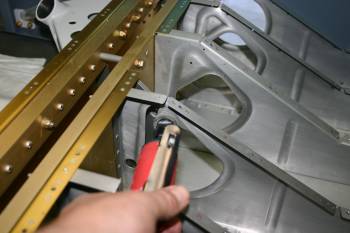 |
Mon 10 January 2005 | |
 | |
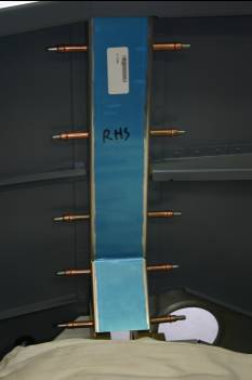 | |
Wed 12 January 2005 | |
| First up was a bit of additional trimming of the rudder pedal weldments. Rather than just trimming 'excess' material firstly we squared the ends. All 4 ends were off and after some attention the lengths came into spec. | 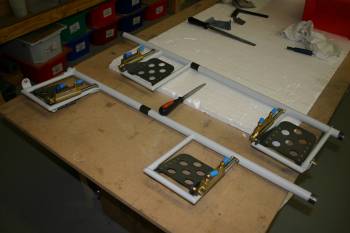 |
| Next we re-visited the rudder pedal locations and mounts. We decided that the rudder actually needed to be mounted and the rudder cables run. After some light cursing, we realised the snap bushing that were put into the fuse a few days ago needed to be removed so that each bush could be squeezed over the forward end of the cable and then re-inserted into the fuse! | 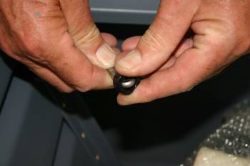 |
| All looks good, and the clearance behind the rudder pedals is better than we expected. One concern was the P1 RHS pedal rubbing on the hot air vent (grey thing on the left of the photo) but in the end no problem. | 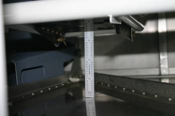 |
| We tested various locations for the pedals, the conclusion was middle location with a 'shorter' joining tab so that the bottom of the pedals are slightly further aft. This also means the brake pedals are angled slightly forward which reduces the risk of riding the brakes during taxi etc. | 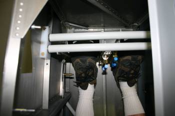 |
| Whilst we were playing with seating position we also looked at possible positions for quadrants. | 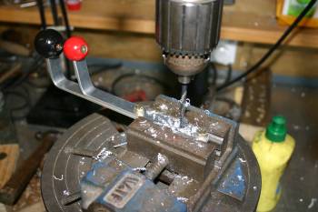 |
Thu 13 January 2005 | |
| Also I finished some of the de-burring of various forward cockpit supports. | 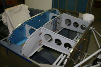 |
Mon 17 January 2005 | |
| Dad worked on canopy latch or more specifically the skin. Some of the corners were squared and the latch was smoothed. The punched 1/8" material has a slight bow which we continue to try and remove. | 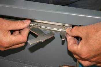 |
| I now understand why the fuel vent line should have a forward bend on the aft rise. The fore-deck panel doesn't fit, rather than trying to re-do the whole fuel line I trimmed the panel. | 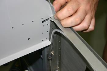 |
| As part of the preparation for the instruments, I want to provide a level / true platform. I carefully marked and drilled several locations for nutplates. | 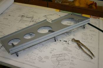 |
| The rest of the afternoon was spent setting up the forward deck. I also cleaned / smooth the weather sill platform. | 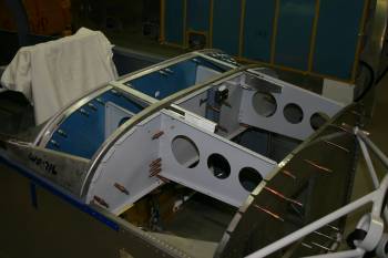 |
Tue 18 January 2005 | |
| Next item was the 4 rudder pedal links. We ended up with 2 3/8" between holes. |  |
| Dad then moved back to the canopy latch mechanism. |  |
| We decided to drill the brackets and back drill the skin (vs the 'standard' way drilling through the skin first). |  |
| My limited input for the day was some forward cockpit structure. I drilled the forward brackets and match drilled the tip-up forward canopy skin. |  |
Wed 19 January 2005 | |
| I continued with the cockpit panel fittings. The air vents needed some brackets made and the plastic supports and vents needed trimming / shaping. | 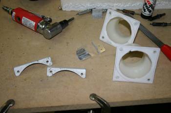 |
| The upper panel supports were no problem, however the lower brackets were difficult to drill. | 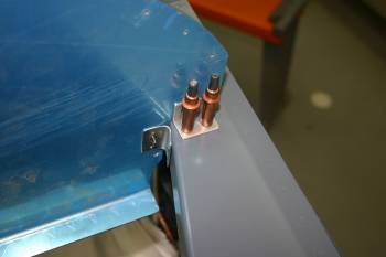 |
| I ended up using #40 pilots from measurements and marking and then back drilling with the angle drive and #30s. | 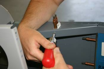 |
| The final combination of panel supports and air vents. The side brackets haven't been drilled to the skin yet. | 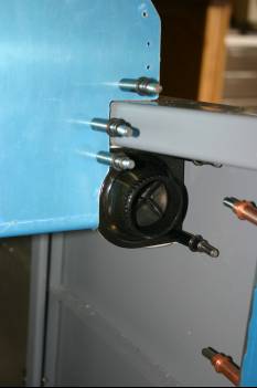 |
Sat 20 August 2005 | |
| Whilst I've been away VANs have updated the tip C channel that goes between the roll-over bar and the rear bulk head. We were just about ready to start drilling but luckily hadn't. These are the new pieces, it includes pre-punched section, the angled cut and the tabs on the aft end. Normal drill - deburr, smooth..... | 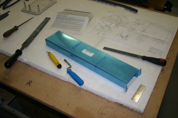 |
| New part cleco'd in. Priming will be a little way off as we are in winter and the temps are in the max 10-15 degree C on a good day at the moment. | 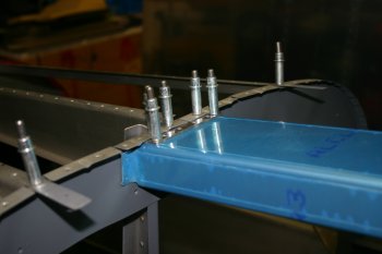 |
| I spent the rest of the day pottering around, getting back up to speed on the jobs at hand.
After I left Dad finished some of the priming of various parts that would otherwise ready for final assembly. One other item that I've seen on another website is the extension of the panel via a C channel. This is just clamped in as a look see. I think it has some good merits - particularly if all the switches / breakers can be held here and the 'avionics' are separate in the panel. | 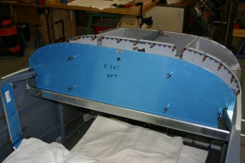 |
| Little job of finishing the panel mount brackets. I was just about to rivet the nutplates onto the angles and I remembered Dan commenting on the sequence being important. It is - rivet the angles to the fuse fist and then squeeze the nutplates on - otherwise you can't get access with the rivet gun. | 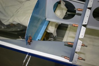 |
| Finished widgets. As per usual - cleco the panel in and it is rock solid. | 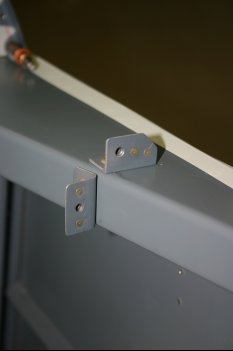 |
Sun 21 August 2005 | |
| Most of today was spent experimenting with various scrap solutions for the cockpit layout, not many photos and lots of thinking time.... . The first half was spent with the quadrants, the second half with the new switch bar that we are hoping to use beneath the main panel. | |
| It took a couple of revisions to come up with a side panel that I think will work. I'm getting used to knocking up a CAD drawing and then prototyping from that. This is an enjoyable aspect of the project - not following any particular 'standard' plan and developing the custom aspect of the aircraft. It does however eat time at an alarming rate - but it will be worth it. | 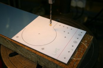 |
| This is the current best revision, the cross-member with the switches / breakers etc will go behind and be riveted to it and along the bottom will be a piece of strengthing 1/8" angle which will also provide the mount points for the quadrant cables - or at least that is the plan at the moment. | 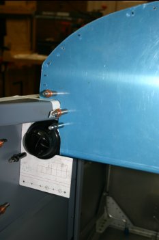 |
Mon 22 August 2005 | |
| Started the day by carrying on with the vent / switch bar support for the RHS. As always the second one was significantly quicker as I knew what I was aiming at. | 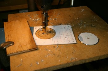 |
| The plates completed, and switch bar held in place. It will have fixtures between the panel and the face plates on left and right. | 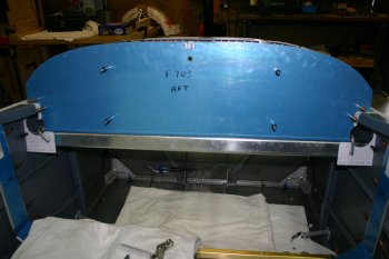 |
| Next was the trimming of the switch bar for the plastic vents. A one shot job as I didn't have any other material of similar shape. | 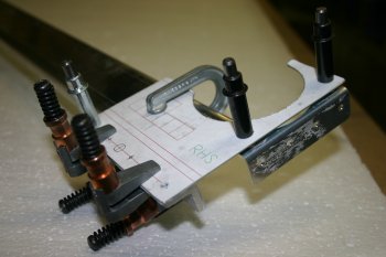 |
| This was the mixture of guesses - I ended up doing a mini-drawing for it to get it right in the end. It was fairly close to the black line as the thickness of the vent otherwise interfered. | 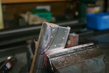 |
| The finished result - all looks good and is solid. Only problem could be getting it in / out. I think it may be a permanent fixture and will have to be riveted in place - I'll investigate further options tomorrow. I also re-looked at the quadrant mounting - I think we now have a plan, some workings to complete tonight and tomorrow I'll try modifying the parts. If it all goes belly up I'll re-order the parts later in the week with other stuff. | 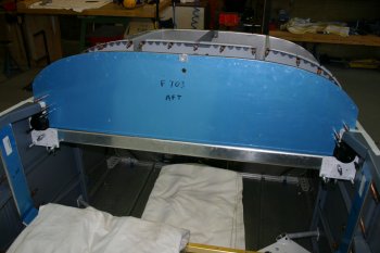 |
Wed 24 August 2005 | |
| I continued with the quadrant mounting thoughts and planning. Using a bit of scrap I mocked up the bracket I was planning on adding to the vertical covers. This was the best position we could find. | 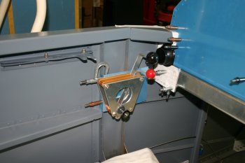 |
| It is high enough to not catch the legs, lower enough to miss the canopy latch and the right distance away from the shoulder to not end up twisting. It is another one of those - "I think this is right - but I won't know until after X hours flying it". Looks about right. | 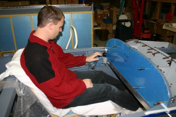 |
| Then it was transpose the design onto the covers and get everything lined up. | 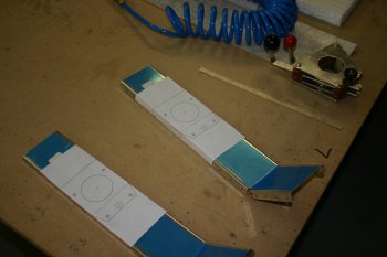 |
| The finished result. Rock solid and looks good - the switch bar plates also seem to line up nicely (nice coincidence huh? :-) and will provide a solid fixing for the Bowden cables. | 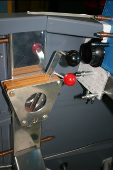 |
Sun 28 August 2005 | |
| Whilst the roll bar was off I took the chance to sort the strike plates (LHS & RHS). I used the normal 1/4" in the corners and then saw and files. Just takes time as it is very visible. | 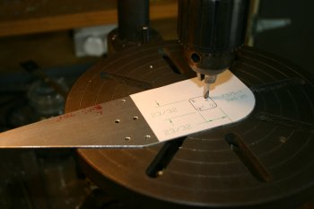 |
Wed 07 September 2005 | |
| Another bitty day. The stick boot plates needed fabricating. Two parts, mirrored. Normal sort of deal, shape, de-burr and refine. | 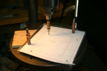 |
| Drill, sabre saw, file and deburr. And prep ready for the pile for spraying. | 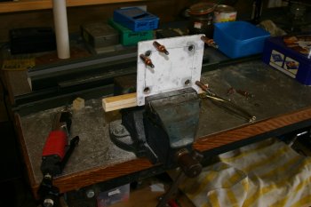 |
Tue 04 October 2005 | |
| Also prep'd parts of the canopy frames. All slow and steady progress..... | 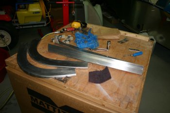 |
Wed 05 October 2005 | |
| I was otherwise busy today, however Dad got a bit of time on more prepping and some work on the rear rollbar C channel. This will be for flush mounted light for the baggage compartment. | 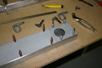 |
Fri 07 October 2005 | |
| This was the finished product for the baggage light mounting. The light is on a swivel allows fore / aft and left / right direction. | 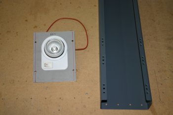 |
Sat 15 October 2005 | |
| Misc riveting nutplates etc. |  |
Mon 24 October 2005 | |
| Dad had a half day working on the arm rests. One of the things I've seen is RVs tend to be susceptible to have arm rests bend, particularly as 'non-owners' get in / out and step on the arm rest. I've seen a number of options, mainly around using a piece of angle / stiffener on the inboard edges. The solution that we are trying is to use another pair of arm rests switched from Left / Right side and a tie together strip. The outboard edge will also be riveted to the skin. This should make a box section which will be STRONG. "Side impact bars" - also it will hopefully provide a mount for holding things like the P2 stick when not in use. | 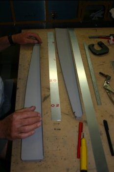 |
| This shows the location / principle in action. The upper rivets will be blind, more marking / drilling needed tomorrow. | 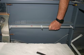 |
Tue 25 October 2005 | |
| Dad continued with the arm rest reinforcements. Jig drilled the end and centre locations and then rivet fan from there. | 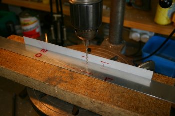 |
| A spacer was made to be used between the two surfaces which means the parts can be clamped together tightly. | 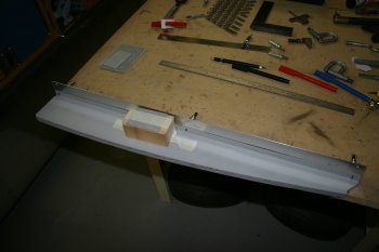 |
| Then it is clamp and drill. If you are doing something similar to this - take care the lower structure is as far aft as possible, we used #41 drills to start with until everything looked OK. | 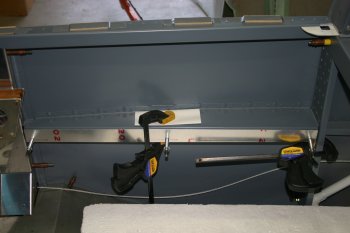 |
| Then of course there is the 'other side' to be done - this is the P1 side. | 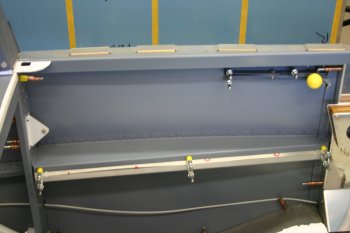 |
| We chose to go with 'oops' rivets (AD4 shank with AN426AD3 heads) as the bottom structure had been previously drilled & dimpled for AD3s which made alignment slightly harder. | 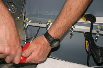 |
| The external rivets to the skin need dimpling - this is a slow process with the pull dimples but it does work. | 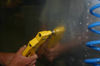 |
| The finished internal layout - upper will be CS AD3 blind rivets, lower will be AN426AD3s. | 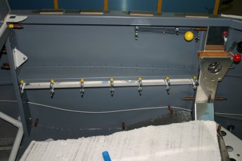 |
| The external layout - just looks like an extra line - someone would have to be pretty up with RVs to notice the difference externally. | 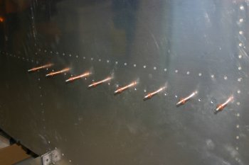 |
Wed 26 October 2005 | |
| Dad finished off drilling / dimpling the P1 side first thing. | 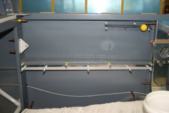 |
Thu 27 October 2005 | |
| Dad continued with the arm rest sections - we have decided to mount the mic / headset jacks on the lower outboard aft end of the arm rests. A doubler plate will provide the support for the jack sockets and also the base of the rear lower rib. | 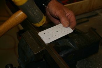 |
| Then a simple case of fitting and drilling. Enough space has also been left for future developments - eg. ANR power and O2 feeds - if and when we want them. | 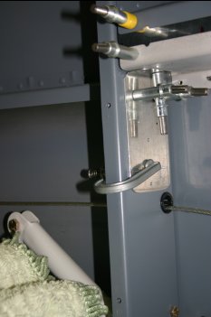 |
| The extra support - being final drilled and dimpled. | 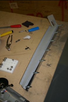 |
Sat 29 October 2005 | |
| Then with the weather playing the game and no wind we went to a mini-spraying session. Included were a number of parts for topcoat. | 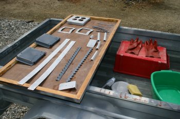 |
| Next up for me was the canopy frame again. Cleco'd everything back together and ready for brace drilling. | 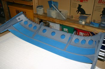 |
Sun 30 October 2005 | |
| Dad started with a simple riveting job, getting the lower assembles for the arm rests together. | 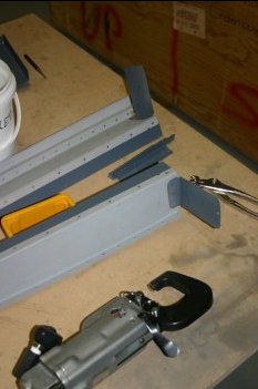 |
| Using some J section two lengths were pre-drilled as upper surface braces. | 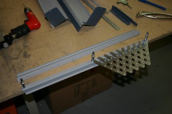 |
| The stiffener was positioned mid way between the two side surfaces at the forward end and about 2/3rds of the way in from the rear end - this seemed to provide the best support. | 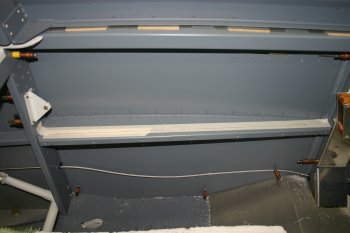 |
| Then match drilled the J section to the upper arm rest surface. | 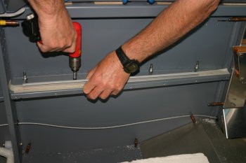 |
| The finished sub-assembly. Just top-coat and pop rivets / skin rivets to complete. That can be left until later. | 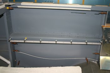 |
Fri 04 November 2005 | |
| Dad was also away today, so I pottered around doing bits. One thing on the list has been the 'nuts' for the quadrant friction controls. Basically we need 2 captive threaded sections that can be flush with an outside surface. Fairly simple contraction; got some stainless steel, put a stepped ridge on it of the right size, and centre drilled it on the lathe. | 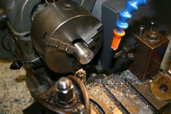 |
| Then removing the chuck from the lathe and putting it on the pillar drill made 3 outrigger locations for keeper rivets. | 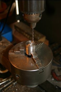 |
| Countersunk for the dimpled surface. | 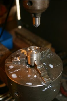 |
| Taped a 10-32 thread in the center. | 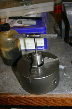 |
| And then parted about 1/4" off. Then repeat for the second side. | 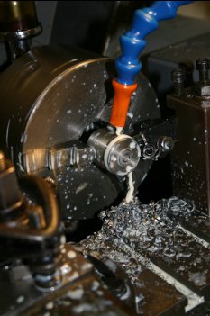 |
Fri 25 November 2005 | |
| Also cleaned / deburred the 5th pt harness mounting. One difference is the default layout isn't going to work with the Hooker harnesses that we have - the standard gap is 1/8" - we need about 7/16" - some thought needed. | 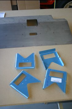 |
Sat 26 November 2005 | |
| Next I continued with the crotch strap mounting points. We need to modify the standard VANs kit to get the extra width for both the mounting bush and the webbing thickness. | 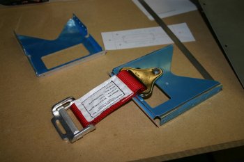 |
| I drew up the applicable area in CAD and laid out the 'right' locations for the upper nutplates - the problem is the edge distance is too small, so a re-jig was needed. The end result is the strap comes about 1/8" forward of the centre of the floor pan hole. | 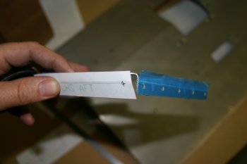 |
| Then rigged the aft P2 plate and drilled / cleco'd with the angle drill. The next stage needed two spacers of 7/16" - so the last part of the day was spent sorting that. |  |
Sun 27 November 2005 | |
| A fresh day - and the blindingly obvious struck early on. Rather than struggling with a full floor pan, I match drilled some scrap that located everything but still provided complete access for drilling. | 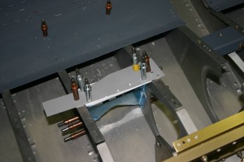 |
| This meant the both plates with spacer were able to be rigged and then simply drilled to the fuselage ribs. One note: make sure the forward / left right is checked on the scrap copy! | 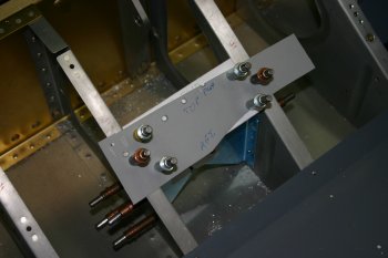 |
Mon 28 November 2005 | |
| With the cool morning - I finished the P1 harness bracket. Simple alignment / drilling for AN4 bolt. | 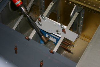 |
Thu 08 December 2005 | |
| With the temperature not great (and even some rain around) we flagged the canopy work for today and I went searching for other things. One item in the last VANs order was some push/pull controls for the quadrant. It looks like the mounting location should work OK, but the AL angle I had wasn't big enough. New revisions being worked on - all custom design - so takes a bit longer. | 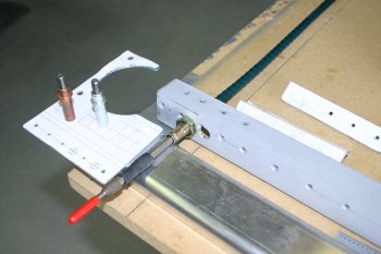 |
Sat 10 December 2005 | |
| Then rain and temp drops - so I returned to the quadrant cable mounts. This the revised test version, made from 1 x 1 1/4" angle. | 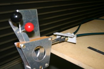 |
Mon 12 December 2005 | |
| Mid afternoon the temps dropped and also some light rain. We returned to the quadrant controls - looks like this will work, surprisingly little support is needed fore / aft. Brackets a job for tomorrow. | 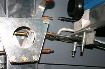 |
Mon 19 December 2005 | |
| Finishing up the day I pop-riveted the crotch strap brackets. A bit of a pain to get the puller into the gaps but solved in the end. | 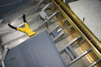 |
Sat 07 January 2006 | |
| Finishing up I continued with the wrestling for the quadrant mounting. I think the mount is sorted, the problem is making the bracings presentable in the cockpits. | 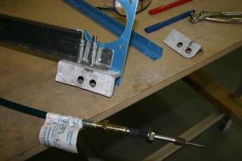 |
| Also sorted the 5th harness point nutplate locations. | 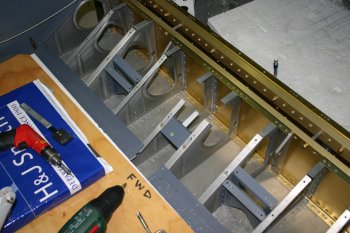 |
Wed 18 January 2006 | |
| Started with a quick removal of the panel and support structures - still not sure how to mount everything whilst keeping it neat, simple and light. | 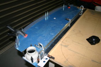 |
Thu 19 January 2006 | |
| On my own today, I continued with the quadrant push/pull cable lower bar cockpit structure. After more thought and a couple more revisions to the plan, I decided to go with two nutplates, it will be nearly impossible to remove the screws without removing the cables but this means I can use the exisiting holes on the cross-frame. | 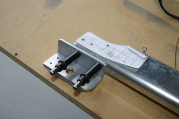 |
| Also sorted the join between the lower edge of the panel and the cross-bar. At this point just #30s, will need opening up for nutplates but I'm un-decided on which side to put the screw / bolt vs. nutplate. | 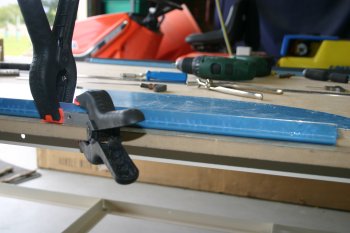 |
| After lots of work and a bit more fabrication, this is the end result. Obviously both sides had to be done also. The small piece of angle provides bracing againt the skin. | 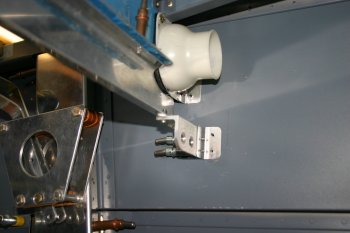 |
| The whole structure is good and strong, I put a single push/pull between the two quadrants which works nicely. The only remaining work is the front sides, we will probably need some form of plates to dress / make it presentable. | 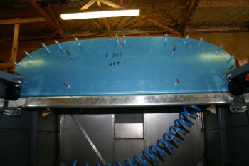 |
Sat 21 January 2006 | |
| This is a photo of the completed quadrant - push/pull system - forgot to get a finished one earlier. | 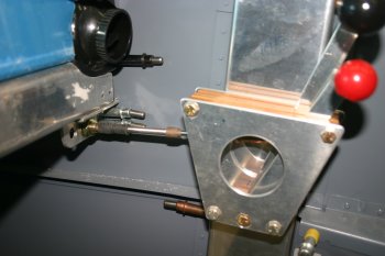 |
| Other misc things completed with countersinking / dimpling / drilling etc - bits work. | 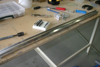 |
Thu 02 February 2006 | |
| Also the quadrant components needed some development - we are shortening the lever length by about 1", so the pivot and the actuation point needed to be relocated. Also the Red 'mixture' control was rubbed down and painted Blue for the prop control (being FADEC and not having any manual mixture control) | 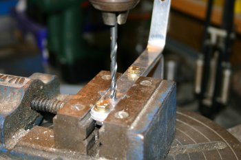 |
Fri 03 February 2006 | |
| Then with the wind coming up, we moved onto other things. I've been trying to work out were to keep the fire axe for a while, I want it close to the P1 side, but out of the way in normal operations. This is the rough planned location. | 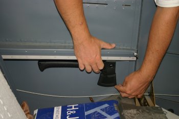 |
| Dad sorted the RHS arm rest with some backing plates for the P2 control stick. | 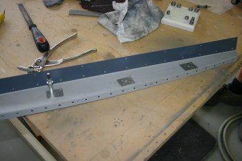 |
| And I came up with a couple locations to be beefed up for the axe mounting. As always, a minor modification or 'bit' ends up taking an hour or more to fabricate / sort! | 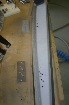 |
Sat 04 February 2006 | |
| A short day today with social commitments, but we managed to get a good batch of priming completed. Normal AllSol / scuffing process. |  |
| Then de-oxidine to acid etch the surface and clean an remaining contaminants. |  |
| It was still fairly early (pre-smoko (<10am) so the Otago sun drying was taking a little longer. |  |
| Dad did a large batch of mixing and then had to finish for social preparation. |  |
| I continued etching and drying. |  |
| Then it was into spray mode, back into a groove - getting better at judging paint feed rates. | 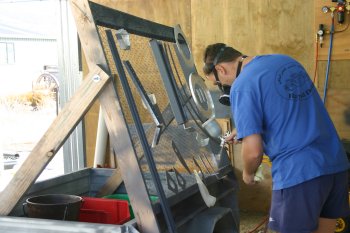 |
| Some of the resultant parts, mainly cockpit bits, but also some fuselage and spinner components. The wind then started to come up, so top-coat will have to wait for tomorrow. | 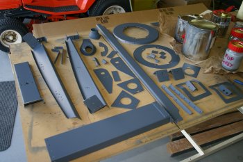 |
Sun 05 February 2006 | |
| Another social / short day, started with riveting a few of yesterday's bits. Arm rests and spinner plate among other things. | 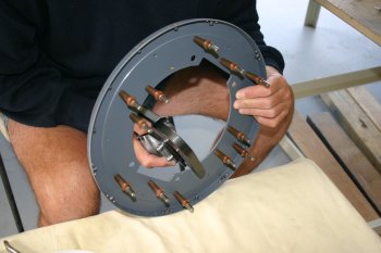 |
| Then it was a bit of touch-up work for the priming and then onto top-coat. | 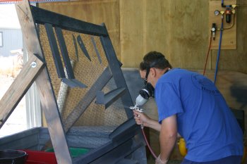 |
| Dad did the mixing and sorting again, I just did the spraying! | 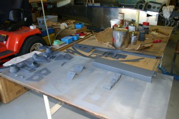 |
| Most of the grey top-coat went on OK after we upped the feed rate the surface tension allowed the paint to spread better. The problem is if you wait slightly too long during a pass, the paint runs badly.... Practice definitely helps. | 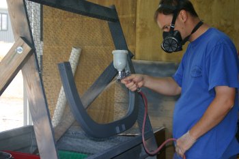 |
| The days product, some of the 'detail' parts we've decided to paint black, not sure yet if the low gloss / matt will work OK. | 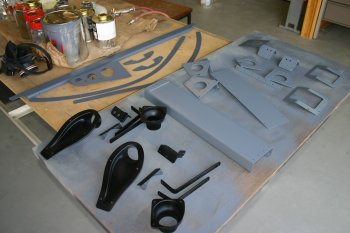 |
Mon 06 February 2006 | |
| Some misc cleaning up done first thing, then more spraying / top coat work. Afternoon off with social stuff.... A few half days recently, good to do the social thing, tomorrow back into it. |  |
Tue 07 February 2006 | |
| Dad removed all the remaining parts from the cockpit area and spent some time cleaning the swarf out. | 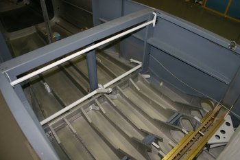 |
| Dad also went around sorting some of the various nutplates outstanding in the cockpit area - bits work. | 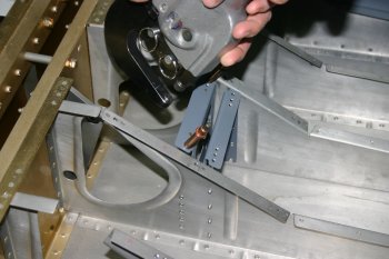 |
Fri 10 February 2006 | |
| We seem to be short of a few non-A (with hole in the thread) bolts needed for the latch system - more bits for the shopping list. | 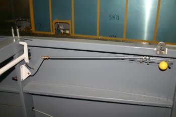 |
Sat 11 February 2006 | |
| Also added a couple of additional fore/aft pass through the main spar. This was the mini-jig that Dad made (note the red cross is where we don't want the hole!) | 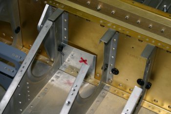 |
| Before the firewall recess could be completed, the rudder pedal bracket need sorting - riveting was a bit of a pain - the structure wasn't really stable enough for shooting/bucking and squeezing was difficult. In the end squeezing was used - some careful selection of dies and a bit of 'persuasion'. | 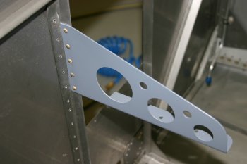 |
| Then a pro-seal session to finish. The original material is starting to go off a bit - not a problem for this work, it is mainly being used as a 'glue'. The new batch will be kept for the fuel tank / senders joint firstly. | 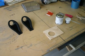 |
| Dad did the messy bit again - NACA vents were first. We ended up using pop rivets with small stainless washers as a backing plate - worked well, I'll worry about if I want to fill / dress the external surface later. | 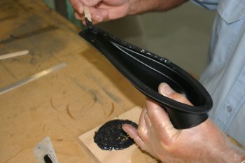 |
Sun 12 February 2006 | |
| On my own today - sorted some nutplates on the centre cover and remade the canopy latch push rod. The previous one had some nasty scores where the tube rotated whilst I drilled / tapped it - new material was ordered and this time I used the lathe chuck to hold the work - much better. |  |
Mon 13 February 2006 | |
| Dad match drilled the aft cover plates, we had to remove them from the QB fuselage to get to the step mounts sorted. |  |
| I bucked the brake valve plate and did the brake lines up finger tight. |  |
Tue 14 February 2006 | |
| Then onto the floor pans. One of the comments I've had from multiple other builders / owners is during maintenance if the forward floor panels are out, it is easy to kneel / bend the forward edge of the fixed floor. Therefore I'm hoping to stiffen the front edge with some scrap J section. | 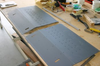 |
| First problem was cutting the J section, snips, band saw and hack saw just ended up trashing the ends. The best solution I came up with was the die grinder - this was quick and neat with just some deburring needed. | 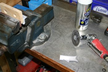 |
| A started measuring everything carefully, but ended up just eye-balling the position and marking a 3/4" gap for each of the floor ribs. | 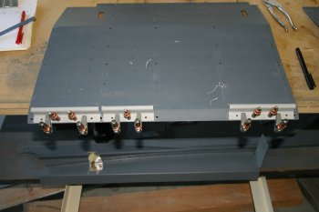 |
| After dinner I fiddled with a new spring catch for the canopy release. The standard bit of bent wire plus spring doesn't look great and doesn't fit that well either. So trying something a little different I tried milling a 1/8" slot in a piece of AL stock. | 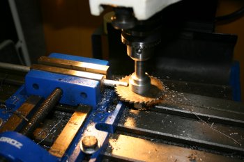 |
| This was then turned down in the lathe. The problem was with the slot it caught on the tool and generated this mess. | 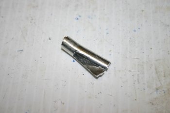 |
| The second attempt was more successful. I turned the outer side down first, then created the slot and finally turned the aft end. The center has been drilled at 2mm and I'll wait until we get a 2mm die and tap to thread the rod onto it. I'll probably cross drill and tap the holding pin, but will need to find a small screw first. | 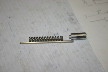 |
Wed 15 February 2006 | |
| Then back to the floor pan stiffeners. The original intention was for the "J" to go aftwards but this leaves a 'barb' going aft which I didn't much like and the very front edge didn't seem to be getting that much extra support.. | 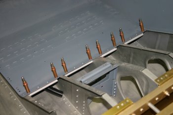 |
| Therefore I flipped the parts around and re-trimmed for the floor ribs. | 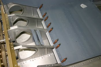 |
| After re-fitting I realised the two locations just aft of the crotch strap attach point where going to be too tight. Therefore 3 face forwards and 1 aft per side is what I finished with. | 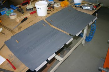 |
Thu 16 February 2006 | |
| Then setup and matched the cockpit side rails and arm rest ready for pop-rivetting. The canopy latch spring location was also drilled. | 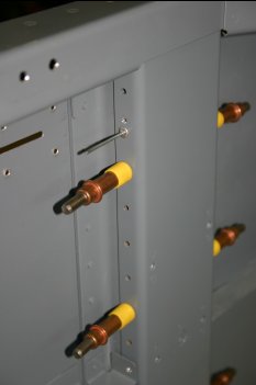 |
| With the new dye available I finished the custom spring assembly. | 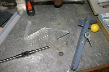 |
| The end result - I'll need to sort a new pivot screw and probably a new shorter spring. The shipped one works - but it is almost a two handed job to move the catch lever.... | 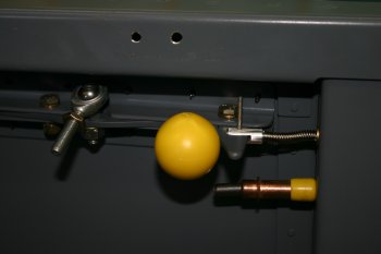 |
Fri 17 February 2006 | |
| Dad spent most of the day in the cockpit areas. Some of the original interior paint spraying didn't work that well and needed to be cleaned and rub down again. | 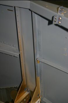 |
| The side cover plates for the spar bulkheads were pop-rivetted in. | 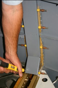 |
| and the arm rest stiffeners were popped on the upper line and squeezed at the back. | 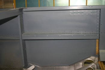 |
| The side skin locations were shot / bucked OK and the resulting arm rests are real sturdy - a recommended solution if you want it. | 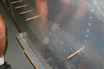 |
Sat 18 February 2006 | |
| Half day with the weather improving, so we decided to get another prime / top-coat session going. Normal scuff, AllSol, de-oxidine, spray. Among other things the main floor pans, seat back stops and rear roll bar were top coated. The plan is to assemble as much as possible in the cockpit area and then redo the internal spraying. |  |
Sun 19 February 2006 | |
| Very short bitty day, only 'progress' was sorting the seat back stops. | 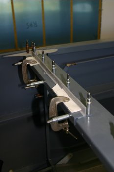 |
Mon 20 February 2006 | |
| On my own today with Dad doing the social thing. The seat back resets were first up, no problems although it makes sense to squeeze the aft rivets before the top. |  |
| Started work on the axe bracket for the P1 arm rest. |  |
Tue 21 February 2006 | |
| Short day, mainly prep'ing for the internal spraying. Dad setup some nutplates on the center tunnel that will hold Adel clamps for cables / static lines. | 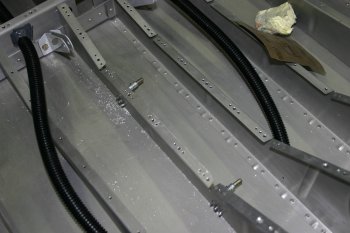 |
| Rubbing down and clean up of the internal surfaces | 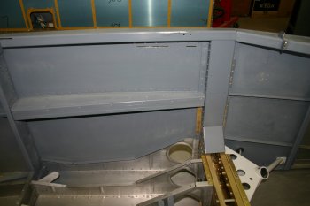 |
| Finished up with fully cleco'ing the floor pans ready for pop-rivetting tomorrow. | 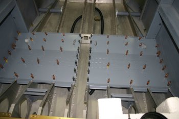 |
Thu 23 February 2006 | |
| Got stuck in with the blind rivetting. The side skins needed holding, but otherwise simple and smooth. | 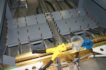 |
| After lightly rubbing down the steel powder coating, the canopy latch was squeezed / bucked. | 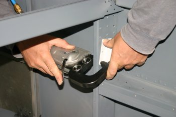 |
| And the rear baggage panels could also be finished, now that the steps were attached for good. | 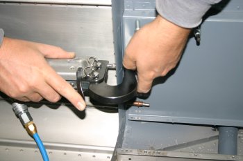 |
Sat 25 February 2006 | |
| Spent most of the afternoon turning down and then shaping the UHMW stock for the axe mount. | 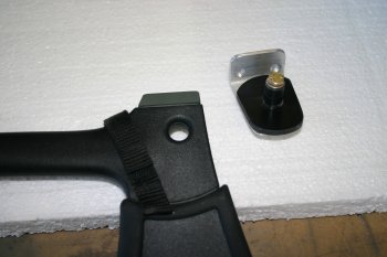 |
Sun 26 February 2006 | |
| After moving the fuse back into the shed, we started attaching a few bits. The vent mounts and custom quadrant were bucked, the P1 sides didn't go that well, but it show by the end ;-). |  |
| Then I started getting bits to put in for the 'last' time. Hopefully we won't need to remove them again, starting with rudder pedals and rudder cables. |  |
Mon 27 February 2006 | |
| I continued with some of the systems components, the control column mounting and elevator push rods. | 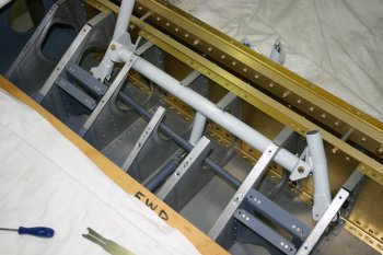 |
| The main static and pitot lines I was hoping to bring through the spar and up forward along the center section - the problem being the supplied pneumatic lines aren't long enough. After a bit of lateral thinking a new route might be possible going up the side covers and straight behind the panel - needs to be checked. | 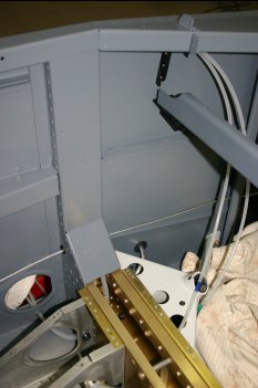 |
Tue 28 February 2006 | |
| With the weather being suitable, we did a top-coat spraying sessions. | 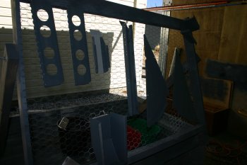 |
| Dad spotted we had missed a few holes on the side rails. | 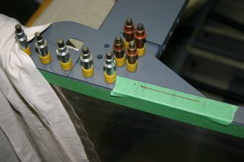 |
Wed 01 March 2006 | |
| Dad sorted the side rails. | 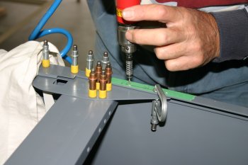 |
| I continued with the rear locations on the striker plates and other misc bits. | 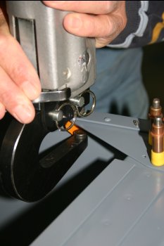 |
| More prep before the skin, tray for the strobe pack was pop-rivetted in. | 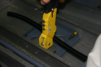 |
Thu 02 March 2006 | |
| Before putting the rear skin on, we dimpled the #6 screw locations. | 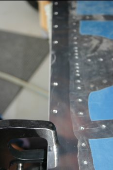 |
| Then clecoed the center 3 top locations. | 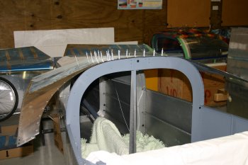 |
| After the two aft center locations were sorts, the upper center aft bracket could be done. I started using the squeezer - BAD idea, didn't set properly and ended up being drill out. Shoot and buck it! | 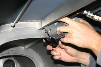 |
| Then continuing with the aft bulkhead, I did the bucking - not comfortable! | 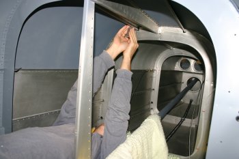 |
| The back half is complete, Dad was suffering somewhat which cut short the day. | 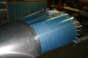 |
Sun 05 March 2006 | |
| A slow day in general, the project seems to be grinding away with limited progress. I know it is all part of the process and to just keep on trucking, but motivation is hard at the moment. Anyway, we continued with the rear skin, the upper locations could be squeezed, the rest were bucked. | 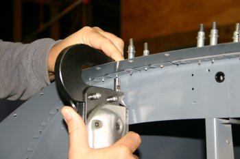 |
Wed 08 March 2006 | |
| Mean while Dad sorted the upper longeron rivets and the rear bulk head. The inboard locations were OK, but the outboard (upper) ones were complete PITA. | 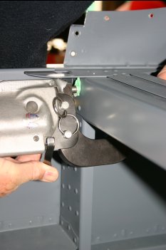 |
| We ended up bucking the last three locations from the other side. I can't see a method of completing all these rivets in a 'controlled' manor. The only thing I can think of is to leave the striker plate until last and that might provide the access needed, however I won't stake much on that being the 'right' solution. The problem is these type of 'challenges' just EAT time, we seem to be plodding along a bit more than usual at the moment. | 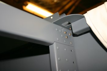 |
Fri 10 March 2006 | |
| Sorted the brake lines, not tightened for final fitting yet, but at least all the lengths and couplings are sorted. | 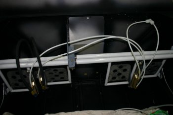 |
Tue 14 March 2006 | |
| Then I started other things, the panel top angle was riveted on. |  |
| The whole foredeck structure was reinstalled. I'm about ready to rivet this in for good, but caution was taken and Dad wasn't around for bucking. | 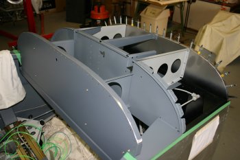 |
| Then it was internal cockpit stuff, the control columns were put back in and the quadrant assembly. | 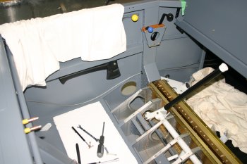 |
Wed 15 March 2006 | |
| A few hours were also spent on other bits, Dad did some adel clamps, I sorted various fluid fittings and misc brackets. The shed was also re-organised which should allow the wings to be reinstalled. | |
Mon 20 March 2006 | |
| One item that has been on the list was the rudder cable alignment. The solution was to tweak the rudder pedal weldment. This helped the 'left/right' alignment, but the RHS still seems to be slightly high. Not sure the best solution yet. |  |
Sat 27 May 2006 | |
| Getting frustrated with the lack of progress on the annunciation problem, I changed for something different. The lower panel bar is slightly further aft now, so the end plates need re-making, not particually difficult but good to actually move forward on something. | 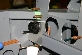 |
Sun 04 June 2006 | |
| Short day, making spacers (rather than washers) and a plastic bush for the inboard support on the lathe. | 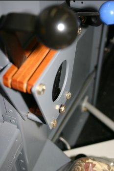 |
Tue 04 July 2006 | |
| Onto the roll trim - spent a couple of hours trying to get the XXXX screws / nuts into the servo and then some temporary safety wire - at least the control stick now holds in a netural position. | 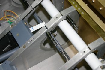 |
Fri 04 August 2006 | |
| Dad had the day off and I spent a few hours cleaning, scuffing and prepping the various bits that have been stacking up over the past few weeks for spraying - hopefully the weather will improve enough to get it done soon.... | 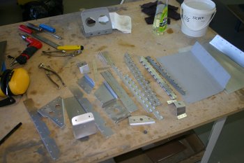 |
Thu 10 August 2006 | |
| Today was a side line project - I need to be able to make 3/4" holes in the ribs which requires the angle adapter - however the unitbit and rotorbroachs don't have a 1/4" screw thread. After a couple of trial runs, I ended up turning two old bolts down on the lathe and made a simple adapter, although it took a bit longer than expected. | 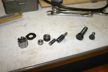 |
| The finished tool - rather than a clever drill center I just used a #19 pilot stub. | 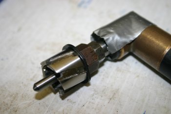 |
Fri 11 August 2006 | |
| Various planning /research for most of the day, but I did sort the center tunnel transition - two 3/4" holes. | 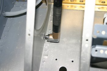 |
| Plus a small piece of conduit - this is below the push rod lowest point and provides a neat method for the lateral runnign wires. | 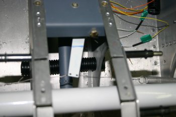 |
Sun 03 September 2006 | |
| To finish the day, I started looking at the stick controls. Then I relealisd that I have the wrong size grips. Note: it should be 1" (P1) and 7/8" (P2), I have 2x 3/4". Some emials sent to Michael Lewis (maker of the wodden grips that Vans & Spruce sell). Update: Mike was really helpful - a few options - two new grips (without switches) is still nearly US$100 and shipping is a pain - I think we will try and modify the ones we have. I'm just annoyed I didn't realise when ordering. | 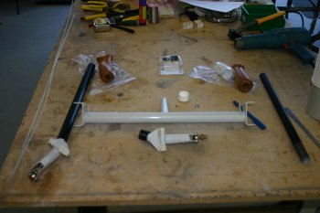 |
Sun 10 September 2006 | |
 | |
 | |
Wed 13 September 2006 | |
 | |
 | |
 | |
 | |
 | |
 | |
 | |
Wed 20 September 2006 | |
 | |
Wed 04 October 2006 | |
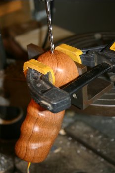
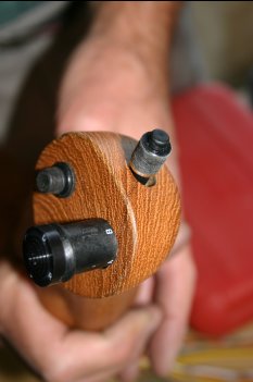
| Dad sorted the two stick grips. Although there is only a single photo, it has probably taken best part of 2 days effort to come up with solutions / tools to drill the large bore holes acurately to the right size. Do yourself a favour and order the right sizes to start with - P1 = 1", P2 = 7/8". | 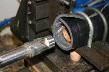 |
| With the new grips - the sitcks were marked and trimmed to clear the lower cross bar. About 5" of P1 (probably 1/4 - 1/2" more than needed) and about 3" of P2 stick. | 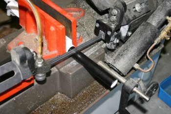 |
| Dad also sorted the P2 stick penetration for the control lines. P1 on the list for tomorrow. | 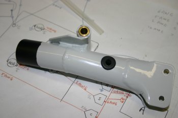 |
Thu 05 October 2006 | |
| With the stick grips now the 'right' size, I sorted the trim / PTT wiring. |  |
| I'm reusing some of the GRT EIS harness that isn't needed. These are pre-terminated and colour coded. |  |
| I roughed out the stick installation. The P2 stick needed a little more trimming - the bolts and washers also need re-looking at. |  |
Fri 06 October 2006 | |
| 2 hours this afternoon was spent getting the inboard bolt into the P1 stick weldment. After finally sorting it - I released I missed the aileron trim bracket which reqires removing the bolt! DOH! Time for a beer. |  |
Sat 07 October 2006 | |
| Brainwave - drill a hole in the tray! Works well and can still pivot it down. |  |
| Another hour (or two) trying to get a single bolt in the front elevator push rod - then I checked and found that is should be a AN960-10L and not the 5703 stainless mini washers (ie. thinner washers). DOH for the second day in a row! |  |
| Also more wire termination and tying. Most of the under seat stuff is done now. |  |
Tue 10 October 2006 | |
 | |
 | |
 | |
 | |
 | |
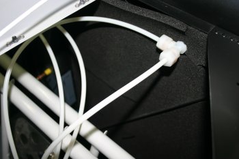 | |
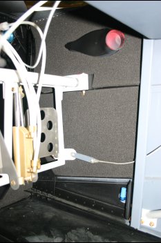 | |
Wed 01 November 2006 | |
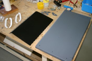 | |
Mon 06 November 2006 | |
| The EL lighting strip comes some 'simplistic' electrical connections. I decided to remove and reterminate completely. A couple of new 1/8" tags soldered on. Also opened a 'slot' between the plastic and AL backing. This was then drilled and dimpled. | 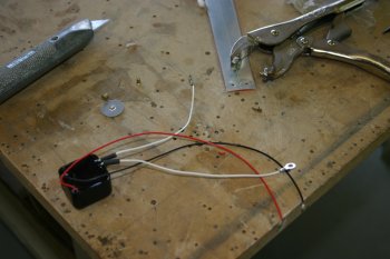 |
| I twisted the AC supply lines and then squeezed a couple of AD4-426's. The flush rivets should mean it lays nicely on the upper surface of the canopy combing. | 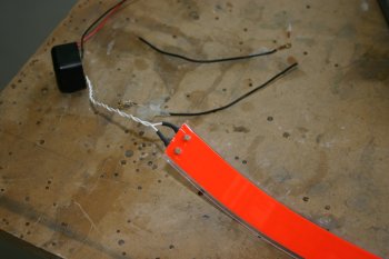 |
Thu 09 November 2006 | |
| Moving onto something different I sorted the mounting of the cover plates for the side vents. I've decided to go with a couple of #8 screws plus the mid location for a extra push-to-talk button. |  |
| After lots of careful trimming, both sides now have a contoured edge and rebate for the switch / XLR connector. |  |
| The finished look, it will make getting the panel in / out very hard but looks neat and tidy. |  |
Sat 18 November 2006 | |
| Finally bit the bullet and extracted the lower cross bar, drilled the push-to-talk locations and prep'd for spraying - in the end the weather turned to custard so I just reinstalled it and the panel. | 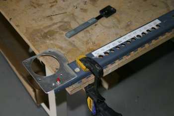 |
| With everything back in the cockpit we got the canopy out of storage. I wanted to check the clearance in a number of places. The only potenial problem is going to be above the top left corner of MFD 1 - but I think will be fine. | 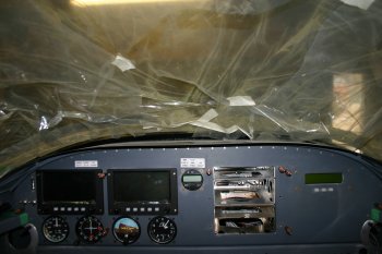 |
Sat 20 January 2007 | |
 | |
 | |
 | |
Tue 30 January 2007 | |
 | |
Fri 02 February 2007 | |
 | |
Sun 04 February 2007 | |
 | |
 | |
Sat 10 February 2007 | |
| As a misc item to finish the day - the floor pans needed a drilling / nutplate added - another thing off the hit list. | 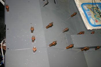 |
Sat 10 March 2007 | |
 | |
 | |
 | |
Sun 11 March 2007 | |
 | |
Mon 12 March 2007 | |
 | |
Wed 14 March 2007 | |
 | |
 | |
 | |
 | |
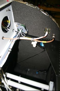 | |
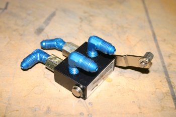 | |
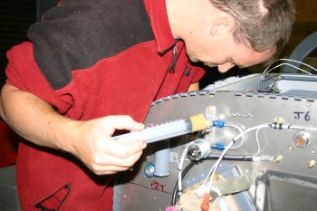 | |
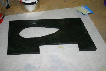 | |
Fri 16 March 2007 | |
| I sorted a minor outstanding item, mounting up the key switch. | 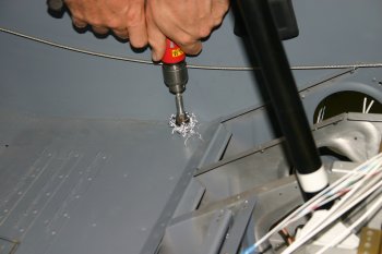 |
| This links the hot bus to the 3rd power input on the GRT AHRS (which means it doesn't loose it marbles when the main busses are off and has time to initialise before start) and also provides power to the starter contactor. | 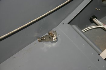 |
Tue 20 March 2007 | |
 | |
 | |
Sat 24 March 2007 | |
| I wanted to retry some of the cockpit controls positions - needed the seats re-installed. The seat backs have a supporting tounge which slides into the cross bar between the main cabin and baggage area. I decided to added a layer of the super slippery, super sticky tape commonly used on the flaps. Only get one chance to apply - but went ok. | 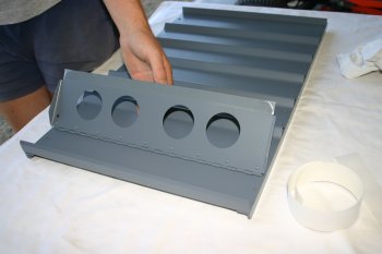 |
Sun 03 June 2007 | |
| Dad sorted the P2 push to talk cabling - just d-pins with heat shrink to hold. | 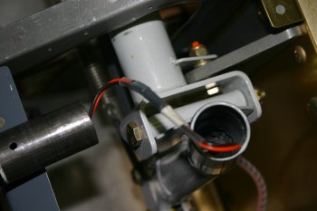 |
| Drilled and fitted a clevis pin and split ring - this holds the P2 stick in - we decided on this solution before the VANs service bulletin. | 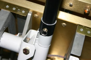 |
Thu 30 August 2007 | |
| Dad did some work on a video camera mount - hopefully this will be located hanging from the C channel in the baggage area. | 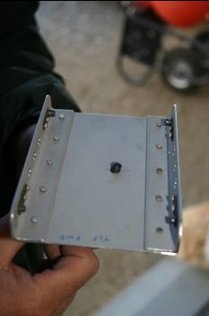 |
Sun 16 September 2007 | |
| Back to winter outside - so a change of subject. I had some scratch material and made a couple of pushrod cuffs. The idea is to stop / slow down the cold draft coming into the cabin and up around the control column.... | 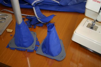 |
Tue 25 September 2007 | |
| Mounted two power jacks for the ANR headsets. | 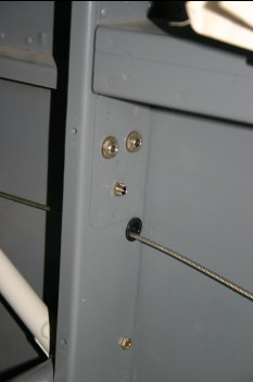 |
Thu 27 September 2007 | |
 | |
Sat 27 October 2007 | |
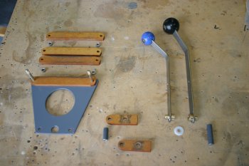
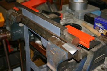
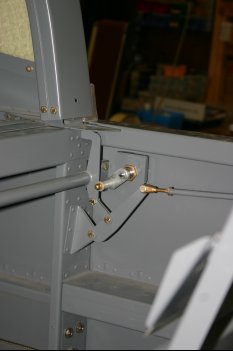
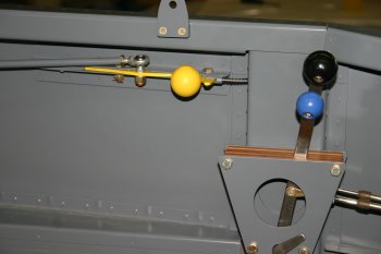
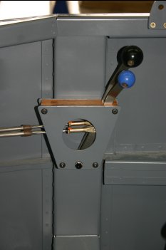
| Dad has been and is continuing to work on the quadrants, trying to get a minimum friction solution that is smooth and doesn't twist too much. | 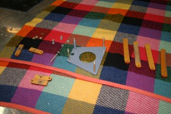 |
Thu 01 November 2007 | |
 | |
Fri 02 November 2007 | |
 | |
Sun 18 November 2007 | |
 | |
Wed 21 November 2007 | |
 | |
Tue 27 November 2007 | |
 | |
 | |
 | |
 | |
 | |
| Home | Carl Morgan | Previous|Next|Latest |