


 |
 |
 |
| Home | Research | Delivery | Empennage | Wings | Fuselage | Finish | Engine | Electrical | GRTDecode | Previous|Next|Latest |
| Engine | Firewall Forward | Engine Build 1 | Engine Build 2 | FADEC | Baffles | Plenum | Cowling | |
Cowling | |
Sat 10 September 2005 | |
| The VANs cowls out of the box don't seem to be a very good match. Particually around the inlets, I think I've read of people heating and re-shaping the cowl, but I need to confrim first..... |  |
| The lower cowl fits pretty well, and the advantage of not having the nose / main gear installed is that a slot doesn't have to be cut until the mounting is sorted. Short day as other domestic things needed to be completed. Weather is also improving so hopefully some spraying might be possible in the next couple of weeks. | 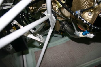 |
Mon 12 September 2005 | |
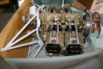
| As our prop won't be here for a few weeks yet and several things are waiting on the cowls, I've decided to go with the spacer option. I know what prop combination we will be getting and VANs state that a 2 1/4" spacer is needed. I used 3x 1" OD plastic tubing spacers. | 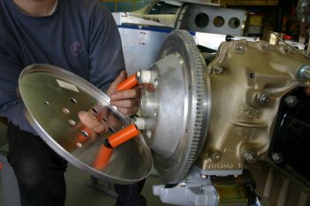 |
| Also checked it was even distance around the whole fly wheel - no problems. | 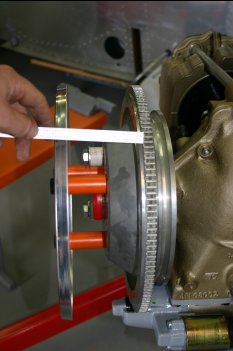 |
 | |
Tue 13 September 2005 | |
| I then moved onto the cowl hinges. The 1/8" hinge is supplied as "9 foot", actually it is supplied as a 6' and a 3' length. The solution is to use the 3' length for the two 11" lower hinges plus the RHS upper hinge (about 12"). The lower hinges wheren't that hard, just take it slowly. At this point I don't have the 0.020" spacer, but I'll get that with the next VANs order. I think I used them by mistake in the wing tip stiffeners. |  |
| Then the side hinges - note the top cowl is taller than you may first think, so the lower cowl hinges stop about 2/3 of the way up the side.. | 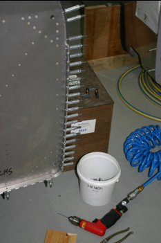 |
| Next was the upper forward skin. This allowed the drilling of the stainless steel firewall on the upper flanges. NB: Boelube works well as a lubricant here. | 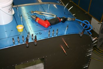 |
| To finish the day I clamped the hinges to the top surface of the skin. This should help shape / bend them a bit over night. Tomorrow I will dismantle and debur etc.... | 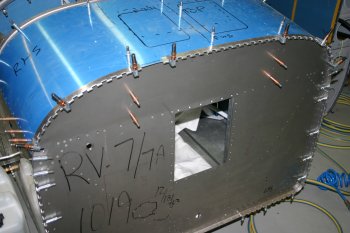 |
Wed 14 September 2005 | |
| I was still on the cowl hinges. The upper skin had to be removed, deburred and preped, along with the firewall flanges. The nex step was to drill the actual upper hinges - nothing too complex, just being careful with alignment etc. |  |
| The cowl side of the hinges also need shaping to help with the arc they end up in. I used the small air driven belt sander which worked well. | 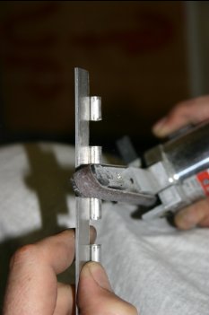 |
| The final step was sorting some hinge pins. I'm still using the original AL cores in some locations and the long term stainless steel pins in others. The SS pins that VANs supplies are probably long enough, just - I think we have 2" spare in 12'! | 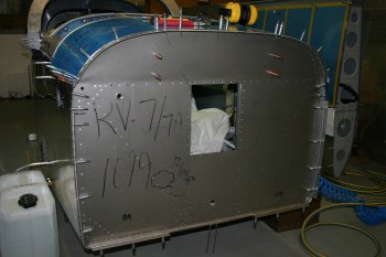 |
| After completing the hinge mounts I started looking at the actual cowl halves. One of the first jobs is the oil door. Some CAD templates to be made up tonight. | 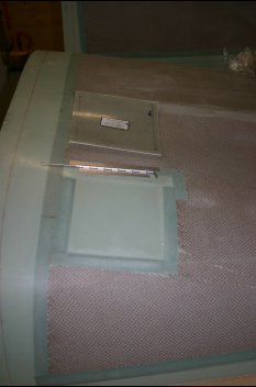 |
Thu 15 September 2005 | |
| First up today was finding the center line and center point of the cowl spiner fairing. I made a template and used a back light to help position it carefully. The top half seems very close to a circlular arc, the lower not bad but some variation. | 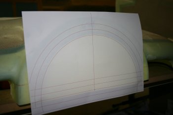 |
| I then moved onto the oil door for most of the rest of the day. Careful layout and plex-glass cutting wheel worked well for the initial hole. | 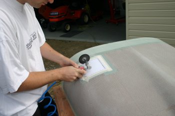 |
| Then it was a slow careful file / sand / shape. The hole is covered when the oil flap is down, but our hands will have to go through it for putting the cowl on and off - so getting it smooth and deburred is time well spent! | 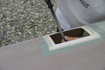 |
| The top hinge is cleco'd in place. I may end up using screws / nutplates to hold the cowl side of the hinge in place. This will provide the chance to replace / repair the oil door if it gets damaged. I've seen several aircraft with this problem and it seems to be simple insurance. | 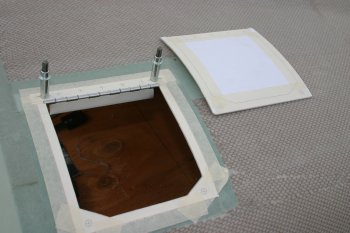 |
| The rest of the day was spent relieving the sides. The cowl material is quite thin but I think I've got it to fit. One thing that caught me out was the door has extra material in some areas which needed to be removed. At this point I haven't sorted the shims to lower the hinge yet. | 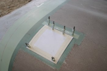 |
Fri 16 September 2005 | |
| The first few hours were spent continuing the oil cover. I made 3 shims - a .020 for the flap it self and .032 & .040 for the cowl side. This brings the top of the hinge flush with the cowl surface. Note: I think the new cowls don't match the drawings, the cowl seems to be significantly thinner than the drawings expect. | 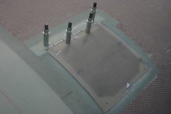 |
Sat 17 September 2005 | |
| I continued with the cowl, the original intention was to sort the upper cowl and then fix the upper / lower join. | 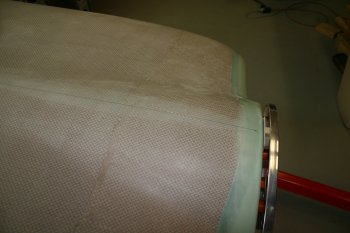 |
| Whilst everything was lined up we marked the center line of the cowl and validated the basic alignment. | 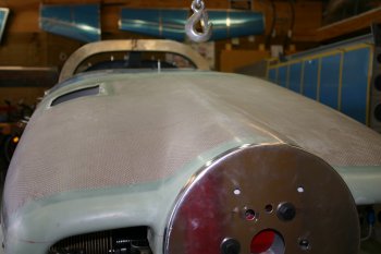 |
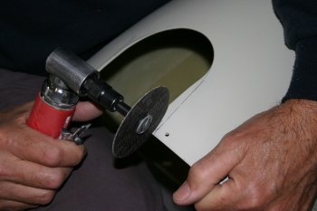
| After some more thought - we decided to start the mating of the front sections first. Out of the box the two halves don't mate that well. The lips around the air intakes fold over and prevent the two halves comming together. Some judicious use of the angle die grinder with a cut off wheel quickly removed the worst of the material and the finger band file enabled some of the other larger excesses to be quickly removed. | 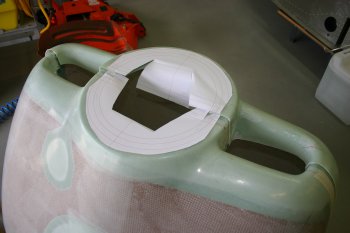 |
| The templates worked well and assisted the alignment of the two halves and top / bottom. The slight surprise was that we will probably need a slight gap between the upper and lower. | 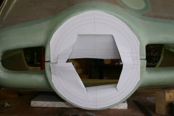 |
| The LHS seems to fit fairly well. | 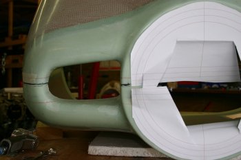 |
| The RHS doesn't work quite as well, the sides are pressed in and riding up. More trimming will be needed. | 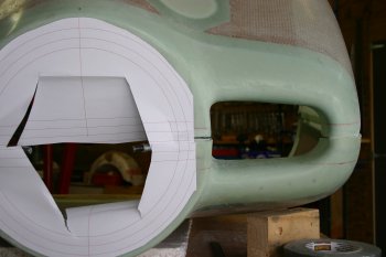 |
Sun 18 September 2005 | |
| The RHS from behind, you can see the trimming of the lip on the outboard lower cowl (upper in photo) has ended up in a small gap, I'm assuming that this can all be glassed later to make it look right. More use of the finger band sander and multiple fits / trims / fittings. | 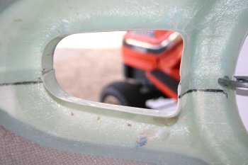 |
| The LHS was better but still needd a bit of tweaking. | 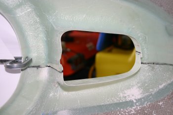 |
| Finally we got to a point where it was close enough for a locating cleco on both sides. Here you can see the gap needed to get a circular front plate - about 1/8". | 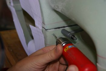 |
| Then it was positioning the upper cowl - a couple of blocks to position the top of the cowl about 1/8" lower than the spinner to allow the engine to sag over the first few flights. | 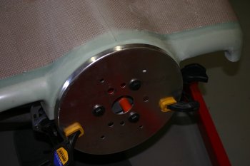 |
| A flood light worked to show the edge of the firewall throught the translucent cowl. Then it is a simple cut off wheel, sand, shape and trim. | 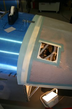 |
| Once the top edge was getting close, I made a small scrap tie plate (instead of using the piano hinge) and fixed a single point on the centre line. With this and the support at the front on the spinner everything else could then be trimmed. | 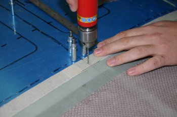 |
| The sides are re-trimmed as they are vertical (as opposed to the 8 degree angle for the upper section). | 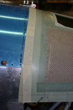 |
| More trimming and sanding and a couple more clecos this time in the long piano hinge. | 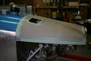 |
| The end result is pretty close - this is the RHS. | 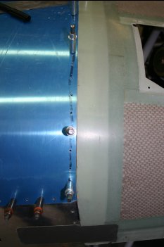 |
| And the LHS - slight gap at the angle point but nothing a bit of filler won't hide. | 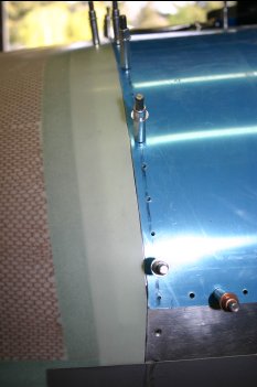 |
| As a bonus the front was in the right place also. | 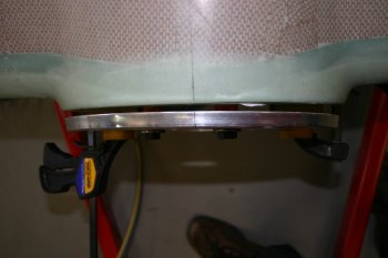 |
| Then onto the lower cowl. After some gaffer tape and more internal lighting. The first cut is the lower edge. | 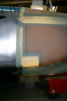 |
| I decided to not trim the exit area - I might consider keeping this but need to understand more of the impacts before deciding. It was getting late - so I stopped before I cut something I didn't want to..... | 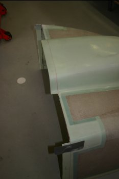 |
Mon 19 September 2005 | |
| I continued with the cowl mating to each other and the fuselage - all day. Slow iterative process, mount, mark, trim, repeat. | 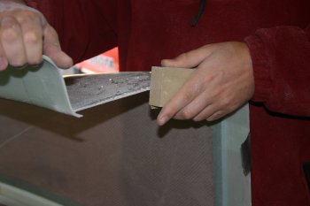 |
| I got the top cowl to an OK state and then taped it down tightly and drilled a couple more cleco locations. | 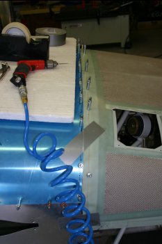 |
| Also moved onto the lower cowl - same deal slow progress. | 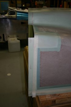 |
Tue 20 September 2005 | |
| Started the day by triming the upper / lower cowl join on the lower cowl. It ended up just above the moulded step. | 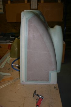 |
| Then after looking at the join I decided to firm up the lower mounting to the fuselage before drilling the cowl-to-cowl hinges. | 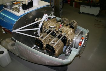 |
| The side hinges were interferring with the 'honeycomb' core. More sanding and shaping needed. | 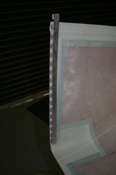 |
| More test fitting and trimming / sanding. | 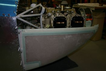 |
| Then lots of setting up and linning up of the long piano links. I followed the recommended upward slope fore to aft. Ended up with the front being level with the top of the hinge and the back being level with the edge of the 'body' of the hinge. I prill drilled the hinge and back drilled into the cowl. | 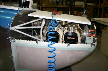 |
| I've decided to try something a little 'non-plan' and use a screw to fix the upper cowl to the top of the rear hinge on the lower cowl. This should tie both parts together very tightly. We will see if I've missed anything obvious here...... | 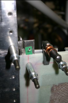 |
| I then removed the engine to make working with the remaining steps significantly easier. | 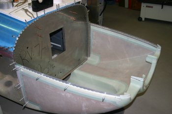 |
| Then I revisited the lower fixing. I'm not that keen on the hinge and it will require a reasonable amount of honeycomb trimming again so I'm considering an option that Dan used with nut plates instead. The other advantage is that we may be able to keep the extra exhaust / cowl exit that goes under the fuselage. I'm not sure if this is a good idea or not, but at least it is an option if we go with tie plate and nutplates. | 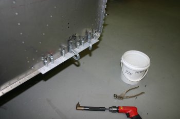 |
| Final step for the day was drilling the upper hinges to the upper cowl. Only 4 locations each side at this point, I'll re-check everything tomorrow and work the front access to the hinge pin. | 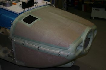 |
Wed 21 September 2005 | |
| More continuing work on the joining of the lower and upper cowl. Slow iterative process. | 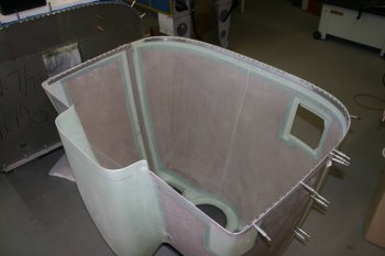 |
| Then it was rechecked on the fuselage. It is getting progressively easier to put on and off the cowls. The top half in particular seems to need a sequence - front, side and rear. | 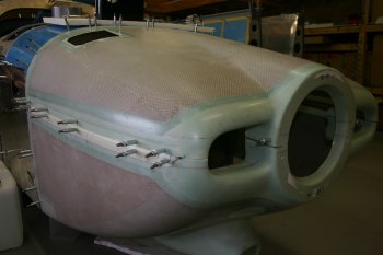 |
| The front join also has the pin which will need retaining in some way. I quite like the method that Walter has used - detail entries here. But mainly I'm not going to do much more until we have the propellor (later Oct at the earliest) and can confirm all the distances. |  |
Wed 28 September 2005 | |
| With the front baffle being the next on the todo list, I decided the cowl needed more trimming. We marked a line parallel with the front of the cowl inlets for the outboard points and just infront of the spinner for the inboard locations (not the left and right are different for the inboard locations due to the prop 'pointing' to the right). |  |
Sat 29 October 2005 | |
| I decided rather than a shim for spacing the hinge / cowl, it only needed a small countersink on the 1/8" hinge. This should locate everything and some pro-seal will provide a bit of vibration support, I think the VANs instructions pre-date the new cowls which are significantly thinner than the original. | 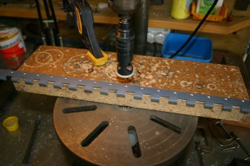 |
Wed 30 November 2005 | |
| Trying the cowl on for the first time with the real spinner location plus the lower hinge riveted to the fuselage things didn't look so good. | 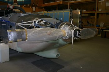 |
| The gap is between 5/32 and 3/16 which is within tolerances. | 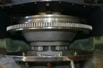 |
| But it looks like the (upper) cowl is about 3/8" too low. | 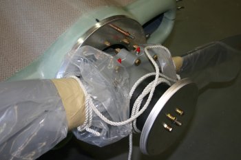 |
| This is the side view, the front surface of the cowl halves are close to 'planar' but needs a bit of tweaking, the gap is OK - bearing in mind the engine / prop will drop in time and the cowl won't move (much). The problem is the difference in the top of the spinner plate vs the top of the upper cowl. | 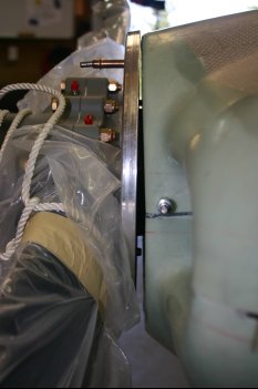 |
| To assist with the cowl work - we removed the baffles as they were just getting in the way, and re-cleco'd the forward upper fuselage skin to make sure everything was held tight at the aft end of the cowls. | 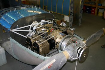 |
| This is the front surface laying on a table reference, the gap is about 1/16" (not much) but enough to look wrong. | 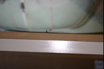 |
| This is somewhere close to where the upper cowl should be.... | 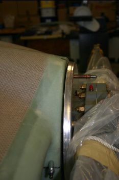 |
| However this leaves some nasty gaps at the rear / sides of the lower cowl in particular. | 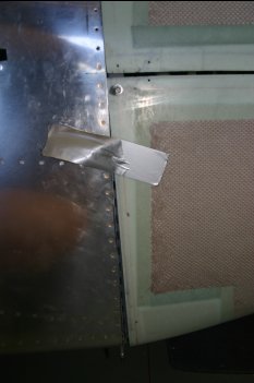 |
| The next stage is really to get the spinner fitted (or at least roughly) and then revisit the cowls - Dad started on the layout / getting two opposite points on the spinner. | 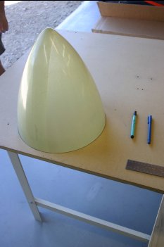 |
| I continued to wrestle with the spacing / alignment. I made an 1/8" spacer and blocks for the lower position of the top cowl, this just showed more problems (partly with the basic moulding). | 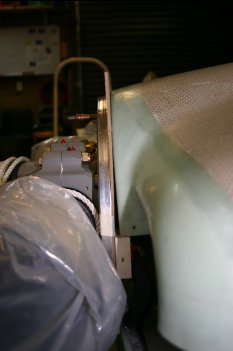 |
| This is the other side from the above photo - one side is good - the other isn't - not a good look.... All in all not a great day - prop has been mounted but cowl is going to need a lot of work. I'm rather down beat about it - I'm sure we will sort it all but I'm disappointed that we have such significant problems. I'm not sure what went wrong (if anything specifically), a day of lots of thinking / puzzling / discussing, but little progress or solutions - time for a beer! | 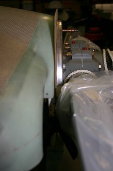 |
Thu 01 December 2005 | |
| With a fresh mind, we restarted the cowl work. First up was getting a repeatable position for the front of the upper cowl. This was done via two 'precision cut' supports. | 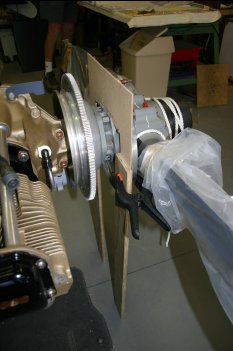 |
| Then the new rear cut line could be marked - I used the same method as we have developed for the canopy work. Masking tape plus sharpie line. This new rear edge allows the front to come up and back a little which helps the 'planar' problem at the front and obviously helps the height problem. | 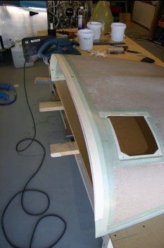 |
| The handheld band sander was used - it seems to result in a straighter edge than hand sanding large changes. | 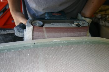 |
| Then after the upper cowl was 'getting there' the lower cowl was attached. The problem was then holding the upper cowl at the right height. A cord sling from the roof rafters worked well. | 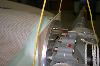 |
| Rather than using the hinge (which can move fore and aft) a single tie was sorted in the center rear location and the forward center line could be matched on the spinner plate. | 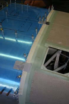 |
| Then the old hinge joint was used to get a rough idea on the lower cowl position. The summary was the RHS was good the LHS was not quite there. | 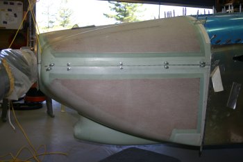 |
| Therefore we went round all four side edges and straightened / levelled them. This has the side impact of helping the rear of the lower cowl come upward slight which helps reduce the rear gap and spinner alignment. | 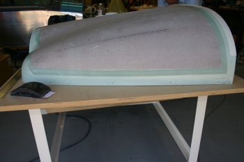 |
Fri 02 December 2005 | |
| Continuing with the cowl, I joined the to halves and refined the joins. | 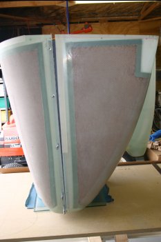 |
| And used the metal tab principle again for the rear locations. The front is still being held by the original #40 clecos that go through the spinner 'circle' and provide the center pivot. | 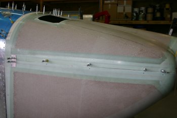 |
| This is the current problem. The magnitude of the gap is reducing, but still about 3/16" at the bottom. I've posted a question to the list about various options available to me and also have a few ideas of my own - I think it is solvable - but it will require some re-work. Having the lower side hinges already riveted to the fuselage may be a problem. | 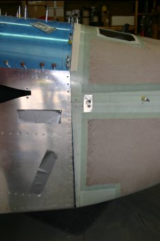 |
| With the two halves mated together, I sorted drilling out the intermediate locations. | 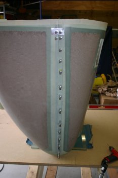 |
Sat 03 December 2005 | |
| Continuing with the spinner - Dad spent some time sorting a template. | 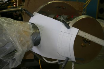 |
| This had to be refined a few times. Why Hartzell don't provide (or I can't find it anyway) a template file beats me..... We got close and I have a copy if others want it - drop me an email. | 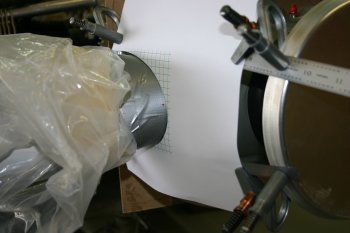 |
| One thing that we have found very useful on the cowls is the original reference lines pre-cutting. Therefore Dad did the same on the spinner - just in case. | 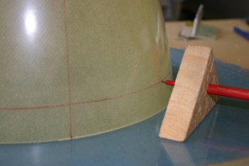 |
| To finish I made the cut outs in the spinner that Dad had marked out. | 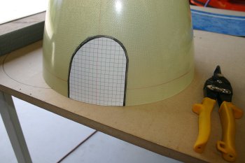 |
| I started with snips - actually worked surprisingly well. In the end I used a sabre saw for the initial cut, plus rotor-burr and finger file for smoothing. The end result fitted VERY well. | 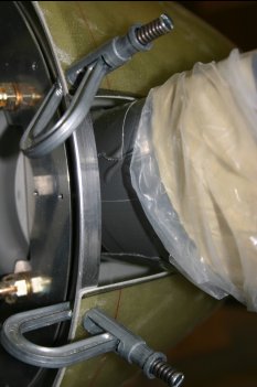 |
| It will need some more trimming just to provide a proper clearance, but a fantastic start. In general after things being a bit down late last week, I'm more positive again, the cowl is coming right. The answers from the list also look promising and similar to my original thoughts. I think we can move the whole cowl backward at least another 1/8" maybe more and hopefully the gaps should 'disappear'. The spinner fits well, the canopy is starting to look like it is going to work and new prop looks great! Oh and summer is starting to happen to ;-) ! | 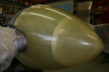 |
Sun 04 December 2005 | |
| Returning to the cowls briefly we remounted the newly re-joined upper / lower cowls to the fuselage. The spinner alignment looks really good. | 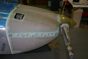 |
| The extra lower cowl trimming is still a problem, first up I think we are going to move the whole structure back by 1/8" then reassess the options. | 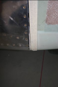 |
Tue 06 December 2005 | |
| Half day with other gardening first thing. Continuing with the cowl we removed a little more of the top rear edge to bring the whole cowl aft slightly. Then lots of re-fitting / testing and re-reading. After more thought - I realised the source of my confusion - the written instruction say spinner 1/8 - 3/16" BELOW the cowl - the drawing shows 1/8" for the cowl ABOVE the spinner. What I had done previously was make the spinner backing plate 1/8" below the cowl. The result is I didn't take the spinner material into account during the initial fitting (BAD), but we don't need to raise the cowl by the amount I thought we had to (GOOD). Then I realised the trimming I did this morning was probably the bit that was 'too much' and NOW I did have a problem! (BAD). | 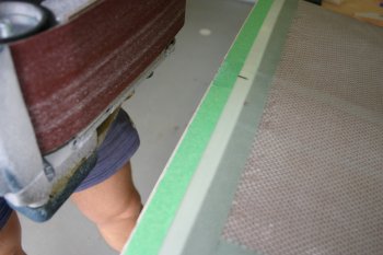 |
| The next step is get the two halves sorted and together then we can move the cowl fore/aft to a suitable place and go from there. Dad match drilled the remaining locations on the hinges to the cowls and I countersunk them. | 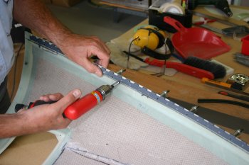 |
| Then it was mix up a batch of resin / silca and glue & rivet the hinges to the upper cowl. Like most things, it gets better with practice - we used a similar approach as pro-seal joints - a bit between each rivet and a bead 'top & bottom' - this reduces the amount of excess on the rivets for the squeezer to get messy with and provides a simple bedding compound. The 'upper' edge was then filleted for a smoother finish. | 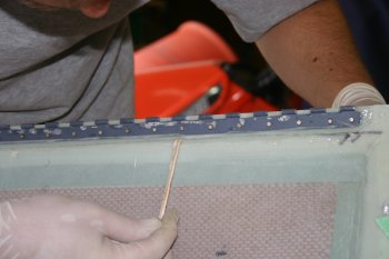 |
Thu 08 December 2005 | |
| Returning to the cowl, we finished prep'ing and drilling the lower cowl side hinges. |  |
| and riveted the hinge on. A layer of resin / silca provides a 'glues / bedding compound' that was filleted along the lower edge and cleaned around the hinge hoops. Once this has cured we should be able to hold the two halves of the cowl together very tightly and complete final alignment / fitting of the rear edge. | 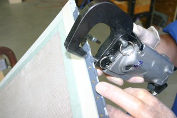 |
| Dad continued with the spinner this afternoon. One observation - the front 4 AN4 bolts aren't 'square' with the prop - not a big problem but worth marking the join NOW, so after hub maintenance (whenever that is) we have a chance of the spinner fitting again. | 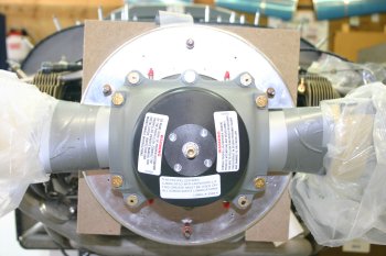 |
Fri 09 December 2005 | |
| Dad continued with the spinner - marking the front plate plane. | 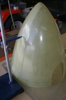 |
| The initial drilling were a little aft of 'perfect', hopefully the others will be able to move forward and by the time we get #19's for the #8 screws they should all be in line! | 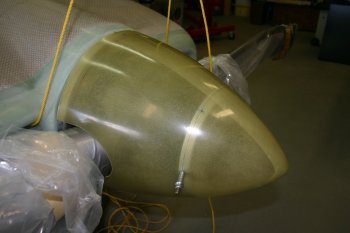 |
| I continued with the cowls, first was tidying some of the resin from yesterday to allow the two halves to mate again and the side pins to go through. | 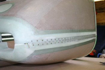 |
| Then it was remount and re-assess the gaps. | 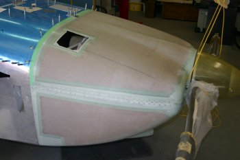 |
| The RHS looks OK, some trimming on the upper rear right edge. | 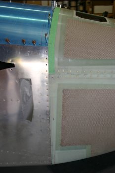 |
| The LHS has a bit more or a problem. I think it is solvable, more final trimming needed first and probably then a little glass work on the bottom / side corner. | 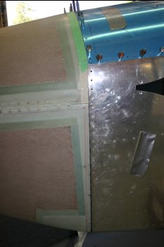 |
Sun 11 December 2005 | |
| Cool start to the day and the engine cowls were up first. To get the top (reference) cowl in the right location we made some more tabs for the upper edge. | 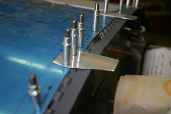 |
| After some more trimming / shaping this is the latest situation. | 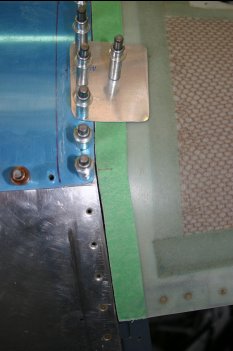 |
| RHS looks good - small (1/16") gap at the bottom, the LHS is a bit more of a problem - about 3/16". | 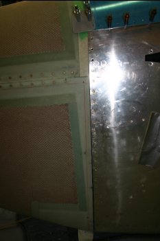 |
| This is the spinner gap - I think the best option will be to increase it slightly, this will move the lower cowl back a little, increase the clearance and still look OK. When the engine drops, hopefully the left/right gaps will balance out and the spinner should (might) end up central in the cowl opening. | 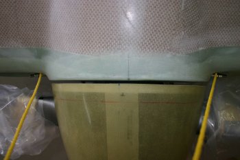 |
Sat 07 January 2006 | |
| Dad was back on project today and returned to the spinner. A jig was made to re-drill the locations as the previous attempts were 'non-perfect'. | 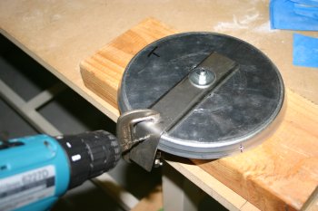 |
| These were then used for the spinner locations and the nutplates were drilled. |  |
Sun 15 January 2006 | |
| After a mishap with the canopy frame (it was blown onto the gravel whilst baking outside - and then the subsequent cursing....) The major part of my day was spent rubbing down the micro-balloon / resin filler / sealer on the upper cowl. In general it seems to have worked quite well, although slightly thinner & fresher resin would probably make it a bit easier to work with and then sand down. | 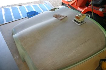 |
Mon 16 January 2006 | |
| Then it was back to the cowls.... |  |
| One area that was causing problems was the left forward baffle floor was rubbing against the lower cowl. I bit more trimming needed. |  |
| Lots of measuring, and small amounts of sanding, getting better slowly. |  |
Tue 17 January 2006 | |
| Continuing on cowl, we got close to a solution and drilled the lower cowl hinges. Once everything is resined / riveted together we can finish any trimming / additional build up. | 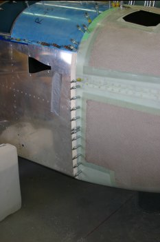 |
| Got preped for flox / riveting of the side hinges. | 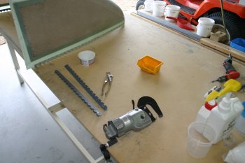 |
| This time I after doing the rivetting I scraped the 'gaps' in the hinge with a piece scrap. | 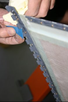 |
| Worked well and kept everything clean. | 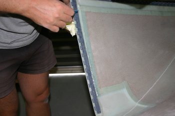 |
| The end result - for drying a pin was left in. | 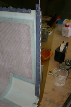 |
Wed 18 January 2006 | |
| Whilst I was in the fibreglass mode, I continued with another layer of micro-balloons on the upper cowl. | 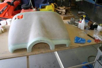 |
| This time I used a really fresh mixture - which definetely helps although I'm still a bit unsure of how much to leave. Currently I'm squeegying (SP!) everything off and just leaving a thin film. I'll sand back tomorrow and see how it works. | 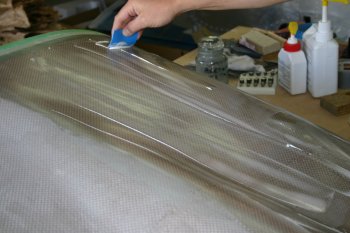 |
Thu 19 January 2006 | |
| Then I spent a few hours sanding the cowl filler back. Slowly getting there, I'm not really sure how good it needs to be before using the EP Filler paint. | 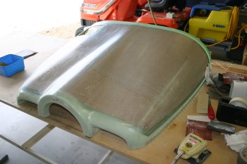 |
| Also put the lower / upper cowl back on the fuselage. The lower cowl is nice and tight and looks like it will be fine. | 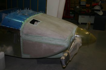 |
Fri 20 January 2006 | |
| I continued with the cowling. The rear upper hinges were drilled and preped for flox rivetting. | 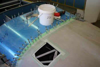 |
| Also did a bit more surface preparation on the upper cowl. One of the problems is I'm not sure how much is "enough" - very difficult to see in the photo, but there are multiple small locations that are still lower. | 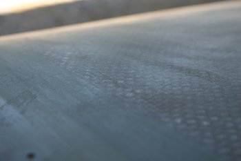 |
| Some parts are fine however. | 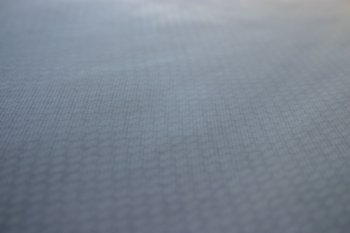 |
| The hinge was simple enough to attach. | 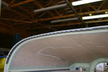 |
| Then I used the remaining resin with some micro-balloons and did some more surface covering. | 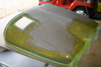 |
Sat 21 January 2006 | |
| I continued with the fibreglass cowl preparation. More sounding of yesterdays micro-balloons to start with. | 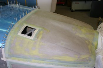 |
| Then another layer of resin / balloon mix, this time however I add 5ml of acetone to the single pump of resin and 'shot' of balloon and brushed it on. This seems to have resulted in a good thin film which I then squeegied. Both sides done - tomorrow more sanding! | 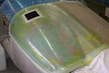 |
Mon 23 January 2006 | |
| I continued with the cowl surface work. | 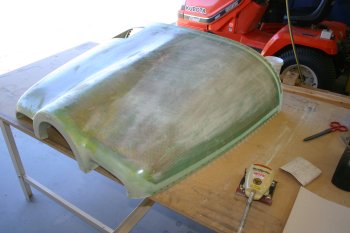 |
| The LHS is now 'done' at least until I've matched the lower cowl to the sides and decided on how I'm going to sort the inlets. I got tired / bored of sanding so went onto 'anything' else. | 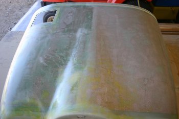 |
Tue 24 January 2006 | |
| I was up and onto the project early and spent a couple of hours finishing the sanding of the RHS upper cowl. Palm sander, plus by hand with 60/80 grit and then 150. | 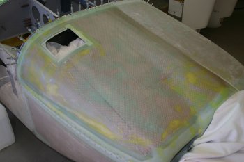 |
Sun 29 January 2006 | |
| Did some prep work on cowls - the next step is the sort the sides, I also sorted some of the rough sanding of the lower half. | 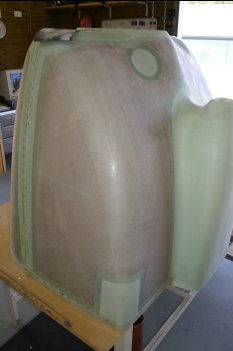 |
Mon 30 January 2006 | |
| With the cool of the start of the (mid 20s) I got the glass work underway. | 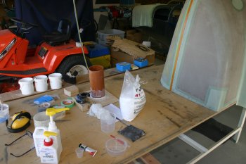 |
| This is the lower cowl sides being builtup. | 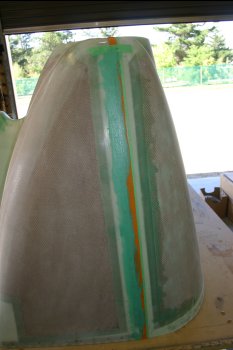 |
| I was fairly generous and then removed the first tape layer to get rid of the excess resin/micro-balloon mix, this leaves an edge in 'nearly' the right place. | 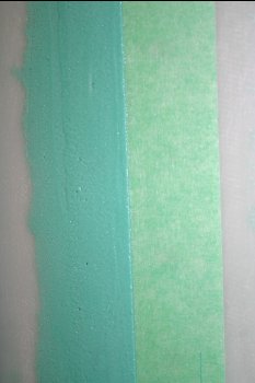 |
| Dad continued with the rear spinner plate, drilling and prep'ing for the nutplates. |  |
Tue 31 January 2006 | |
| Again first thing, more fibreglass work, this time the upper cowl, so masked the lower cowl with masking and electrical tape. | 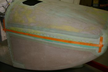 |
| Plastered the upper cowl with micro-balloons and the removed the excess with the tape. | 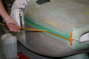 |
| With warm temps early afternoon, the micro-balloons was setting already, it is a fine line between being still soft enough to be able to break the two halves apart (a single large cowl isn't a good look) and set enough to not deform. | 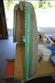 |
Wed 01 February 2006 | |
| Meanwhile, I was back to sanding, starting with the sides of the cowls. | 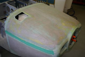 |
| The rough result after 80 grit, seems like a good start, I'll wait until the bottom cowl has been surface prep'd to finish the blending of the edges. Also letting the resin cure fully is probably advantageous. | 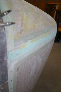 |
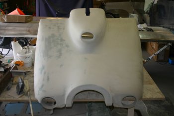
| Continuing with the cowls, I started on the inlets, I've pretty much decided to go the full hog and redo the inlets and provide custom ducts to the plenum. This is quite a bit of work, but should provide a 'unique' look and it is something that I believe is a good engineering solution - I may yet live to regret it! | 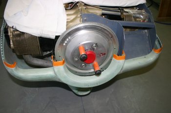 |
| I put the cowl halves back together after using electrical tape to provide a release line at the joint locations and also used some clay to help it specific areas. | 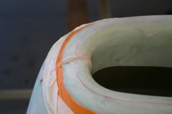 |
| This was the finished masking, prior to glass layup. | 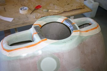 |
| a 2oz, 6oz, 2oz sandwich - hopefully this will be enough to start the process. | 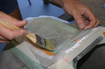 |
| To try and help get a flat-ish surface I used a couple of sheets of baking paper plus 032 AL sheet. | 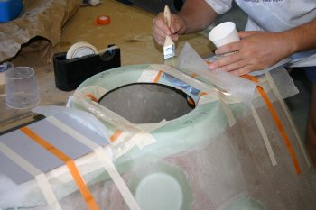 |
| The whole cowl was then turned upside down and left to cure. I'm expecting to leave this for a couple of days and let things really set before starting to drill 4" holes in the front. So I now have a one piece cowl! | 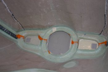 |
Thu 02 February 2006 | |
| I continued with the cowl / plenum work. This was the result from yesterday, it was OK, but not really as flat as I wanted. After various options being considered we decided there was probably a better way. | 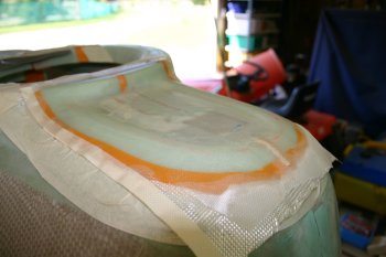 |
| Therefore I cut and ripped off the glass from yesterday - even though it had only had 12 ish hours to cure, it was already pretty tough. The glass ply came away OK, leaving a resin layer bonded to the original cowl. | 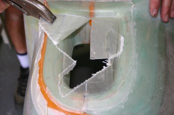 |
| After lots of sanding I got back to the starting point, ready to try again. | 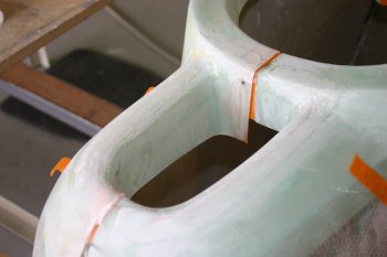 |
| Then back to the cowl, I made two metal supports and rebated the cowl to take them. | 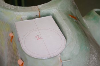 |
| Then a good scuff of the AL sheet (palm sander plus scotchbrite pads work well) ready for silca floxing. | 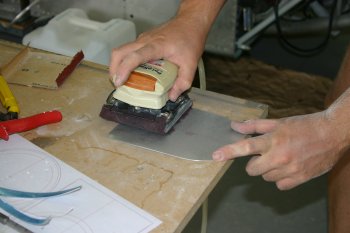 |
| A generous layer of flox and then bedded down the AL sheets. | 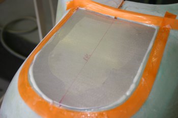 |
| After a bit of tidying, pressure applied from the top and left to set overnight. | 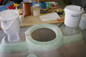 |
Fri 03 February 2006 | |
| Continuing with the cowl, I sanded back some of the excess oozed flox. | 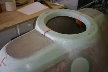 |
| Then pasted up some resin and put a couple of 2oz layers on. | 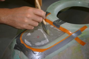 |
| The peel-ply to remove the excess resin and get a flat finish. | 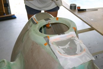 |
| To finish the day, more sanding - a day wouldn't be the same without sanding. I removed the excess material and blended the glass edge back to the cowl surface. Next stage is to let the glass cure and then a large 4 3/8" hole saw...... | 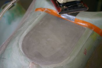 |
Tue 07 February 2006 | |
| I continued on the cowl. This is the monster holesaw (4 3/8"), I opened the pilot location up to 3/8 and then took it slowly with the big hole. | 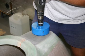 |
| Worked better than we had hoped - nice even, clean holes. | 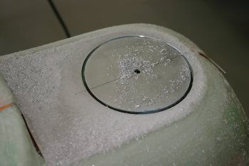 |
| The holesaw didn't go through the way, a pad saw completed the cuts. | 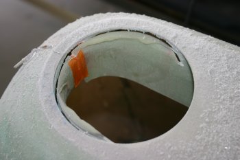 |
| Just for kicks we slide the one-piece cowl onto the engine, the alignment of the new inlets looks ideal, although the path of the incoming air will have to go up about 2". The alternative of 'high inlets' was discounted on aesthetics grounds. | 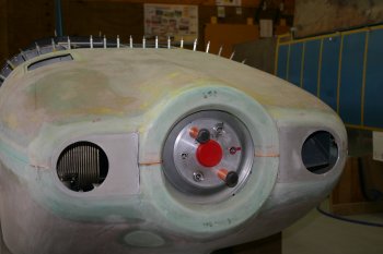 |
| Whilst the cowl was fixed as a single structure I made two 2 1/8" holes on the 'corners'. These will be used for cover plates over the side pins (credit to Walter for the idea). | 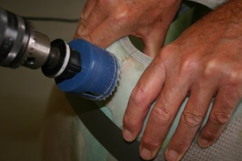 |
| The gap between the edges and the front / hinge is pretty tight, but should work OK once a backing plate has been attached. | 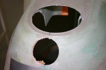 |
| Then I split the halves again. The outboard locations I just used a junior hacksaw, the inner plates I started with the die-grinder and then went to the sabre saw. We decided to go with a tangential line to the openings as this will hopefully provide a smaller 'seal' area between the inlet and upper cowl. | 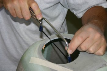 |
| Lots of cleanup, smoothing, filing etc to remove excess resin, clay, AL, sharp edges | 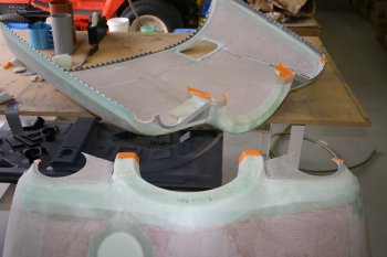 |
| This is the rough path needed for the air, but rather than having a steep 'tube' going up, I'm currently planning a near level entry and then a fibreglass transition upwards and outwards to slow (and reduce the air pressure) as the cooling air enters the plenum | 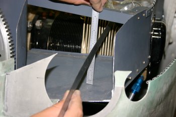 |
| The current template for the inlet - the plan is for a metal tube plus fibreglass mounting on the cowl. The plenum will have a separate fibreglass front (see plenum page for the latest tests) and the two 'tubes' will be joined by baffle material and probably some form of large jubilee clip. | 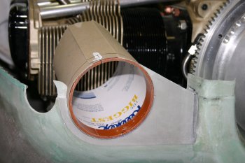 |
Wed 08 February 2006 | |
| I continued with the cowl and inlets. First up I back drilled the doubler / mounting plates to the lower cowl faces. | 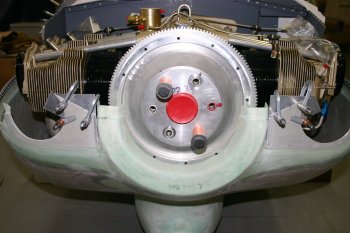 |
| The mistake was drilling from aft towards the front - the glass ply lifted from the AL sheet and created voids. I sanded down a line below the problems back to the AL and removed the fibreglass layup in this area. I'll refill / remake later when I'm doing the inlets. IF you drill from the front aft wards it isn't a problem - lesson learnt. | 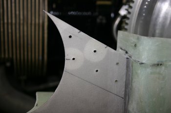 |
| One side benefit of no glass was I could dimple the AL joins. | 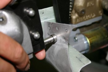 |
| Then it was more shaping to match the 4 3/8" hole previously made. | 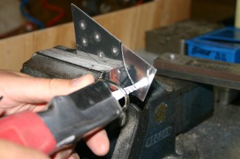 |
| Also trimmed some of the excess of original cowl material to make access a little easier, the remaining 'lip' will be used to glass onto when I do the rear side with the inlets. |  |
Thu 09 February 2006 | |
| First up we glued and riveted the cowl plates together - the Araldite epoxy was used to help the thin corner bond - not structural but needed. |  |
| The Pro-Seal masking tape principle was used again to remove excess compound. |  |
| And a clamp to hold everything whilst it cured. |  |
| Then I went onto making some new inlets out of 025 sheet. This is the result of a couple of hours of hassle - getting a tight tube with the holes in the right place is not that simple. I also had to work a drawing development of a curve for the 1/2" difference between top and bottom locations to help slope the inlet upwards slightly. |  |
| Once the basic tube was done, it was cut in half and profiled for the sloped edge. |  |
| The after riveting result - came out really well. You can see the sloped front on the right hand side, this is good and flat and I can still use the plastic tube as a forma for holding and positioning. |  |
| The new inlets just popped in really nicely to the inlet locations - tomorrow I'll sort some tabs to hold it still whilst I glass it in permanently. |  |
Fri 10 February 2006 | |
| I sorted a couple of locations per side for joining the plates between the upper and lower cowl halves. | 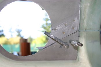 |
| More preparation and alignment - a bit more trimming / sanding also. |  |
| Then onto the resin work, mainly flox (silica mix) to provide a bed around the tubes. | 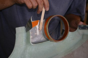 |
| The idea is to get it in a fixed position so that the rest of the glass work can then be laid up later. Generally seemed to work OK - now I need to leave it for a couple of days to let it cure properly. | 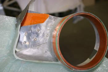 |
Sun 12 February 2006 | |
| Then back to the cowl. With the engine off the two halves are easier to work on mounted on the fuse. The upper cowl is going to need some trimming, but looks generally OK at the front joint. |  |
| Before doing any more resin work, I decided to try and sort the backing plate for the side hinge covers. First attempt was a .025 AL backer - a quick CAD drawing and some interesting hole-saws / shaping. |  |
| However the metal plate was not flexible enough so I went with a pair of 2oz plys - some eyeball engineering and three cleco's - a new version. Hopefully this will provide a basis for an exterior plug to be made for the final exterior shape. |  |
| Then into resin mode - having a second person really helps with keeping the cloth clean. Like lots of things in the project - single person is possible, but two people make it easy(ier). |  |
| The side parts bonded nicely with some flox. |  |
| The front surface was more problematic, I was hoping to have a single ply on the plate and then pulled it into the tubes. The issue was I couldn't get the glass cloth to lay flat on both surfaces, we tried multiple ways but nothing worked. Ended up removing the cloth and cleaning up - rather deflating end to the day. |  |
Mon 13 February 2006 | |
| Meanwhile I continued with the cowl inlets, this time laying up some 2 & 6 oz strips around the top and lower rear surface. This should hopefully strengthen the tubes without adding to much weight. |  |
| A single front surface layer was also added and then trimmed back. |  |
| Before I quit for the night, I trimmed with a knife the RHS inlet glass-plys, the LHS wasn't cured. |  |
Wed 15 February 2006 | |
| The last hour or so was spent on the cowl, doing some clean up on the lower half and shaping on the upper. Not quite done but progress. | 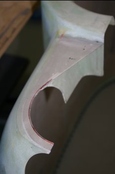 |
Mon 20 February 2006 | |
| A bit more cowl clean up / trimming - this is the top half. |  |
Fri 17 March 2006 | |
| I starting making rough cuts for the lower cowl. This is the first time the front gear leg has been on. I started with a 30mm hole saw and then die-grinder and finger file for trimming. | 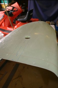 |
 | |
| You can see the multiple attempts that I had to make! | 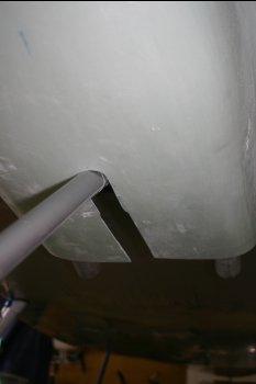 |
| The 'overall look' - a bit like an aircraft! | 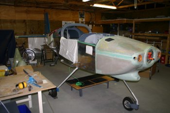 |
Sat 01 April 2006 | |
| The cowl / plenum alignment needs more work - I'm not sure yet how to get a fibreglass shape, current options are clay, foam, on the engine or off on the bench. |  |
Mon 03 April 2006 | |
| I spent for the first few hours today sanding and cleaning up the cowl in lets. |  |
Thu 18 May 2006 | |
| I finally decided that I had to trim the rear edge of the lower cowl. Not a huge job, but I've been waiting for as long as possible. Also spent some time looking back at the exhaust layout / alignment - more options now. | 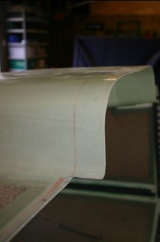 |
| Then moving onto to the lower edge of the cowl - one piece of feedback I've had is the edge can benefit from some strengthening. This is a strip of .032 that I've formed around the edge - the fibreglass needed quite a bit of rebating. | 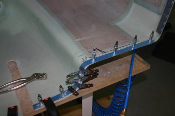 |
| Rather than the standard piano hinge on the lower edge we are planning on using screws, as the link between the fuselage and nutplates I fabricated some .063 straps. | 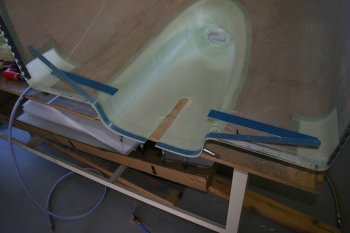 |
Fri 19 May 2006 | |
| Finished the drilling on the cowl side of the brackets. Three locations per side for #8 screws - just #30 clecos at this point. |  |
| Then with the cowl full installed, match drilled the firewall locations. |  |
| The whole cowl is very solid, however I think I'll need to trim the rear edge slightly more to ease the installation of the hinge pins - too much of a mission at the moment. |  |
Mon 05 June 2006 | |
| Today I started looking at the lower cowl support bracket. I like Walter's approach of using adel clamps rather than drilling the weldment so went with a custom bracket. | 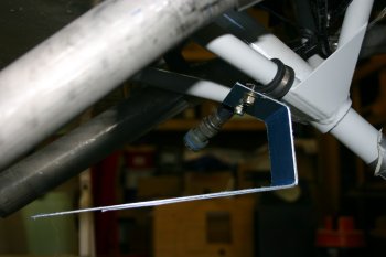 |
| After making the vertical support, the forward bracet needed some 'tweaking' but seems to work over all. | 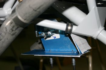 |
Tue 06 June 2006 | |
| Next up was some further trimming of the cowl gear leg openning, even this is probably not enough. | 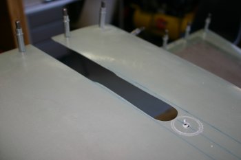 |
| The bottom of the cowl bracket has a spacer, as I have a line of .032 reinforcing strip on the cowl edges, I've upped the spacer to a single 125 bar. | 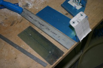 |
Wed 07 June 2006 | |
| I continued with the cowl, more fitting, trimming, refitting etc. | 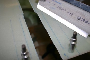 |
| Then drilling / edging / shaping and nutplate fitting. | 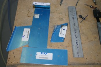 |
Tue 21 November 2006 | |
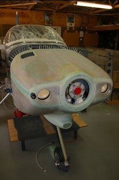
| Put the cowl back on - the most 'complete' the project has looked for a while. | 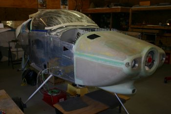 |
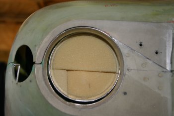
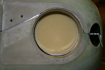
| I decided my previous attempts for the cowl hing pin covers weren't going to work, so out with the sabre saw and removal of the problem! |  |
| Ths part of the new plan - two metal disks, nutplates and covers. |  |
| Along with a couple of spacers (washers), the backing plates can be held with the cowl halves mated. I plan to then glass the back in and then re-finish the outer surface with glass / micro balloons. | 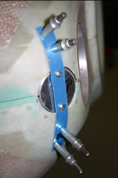 |
Mon 27 November 2006 | |
 | |
 | |
 | |
Sat 02 December 2006 | |
| The lower cowl bottom edge has a stiffener strip, I finished counter sinking and prep'ing the cowl. | 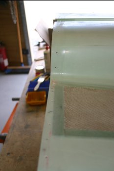 |
| The cowl bottom was flox'ed and stiffener squeezed on - I made one mistake in that I should have put a layer of tape on the inner surface which would have made cleaning it simpler! | 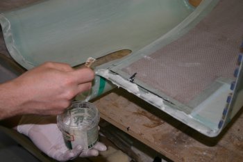 |
| I also added a 2" strip of 2oz cloth on the outside which can be feathered later - peel ply on top of that although not much resin was coming through. | 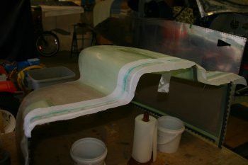 |
Sun 03 December 2006 | |
| After removing the peel ply, then it was out with the pad sander and blending the 2oz glass into the outer surface. | 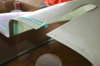 |
Thu 07 December 2006 | |
| Big day of fibreglassing today - multiple batches. First up was the cowl pin covers. I laid a couple of 6oz layers and will let it cure properly, then split and build up further. | 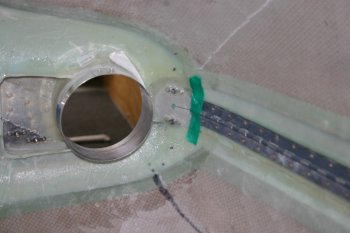 |
Sat 09 December 2006 | |
| Only a few hours today, mainly shaping / sanding and prep for more fibreglass work. | 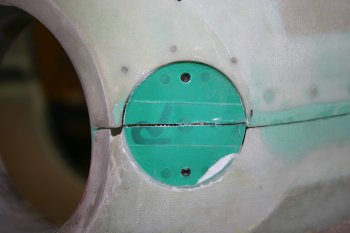 |
Thu 14 December 2006 | |
| Then onto the oil door - more drawings, this time for the hartwell latches. | 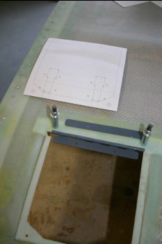 |
| Drill, sabre-saw and files. | 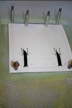 |
| After cleco'ing the hartwell latches on, it is obvious the 1/32" step for the catch isn't going to be enough. I marked the inside of the cowl and decided to just remove the material and build up as needed. | 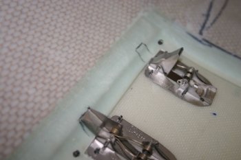 |
| I tried to just cut back the 'latch' areas, but in the end took out a larger area and added some .020" AL stricker plates. | 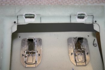 |
| Masked up / protected the cowl and latches for glassing - a double layer of electrical tape seems to work really well, one cured - sand back to the first layer is removed, then peal bak the second (lower) layer for a fine finish. A third layer of tape can be usd to remove excess resin if that is needed. | 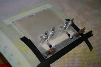 |
| I rivetted the one half of the piano hinge to the oil door and topped with a small piece of 2oz cloth and peel ply. | 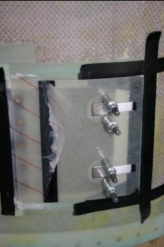 |
| Then the latch recesses - difficult to see in the photo, but a AL strike plate bedded on flox with a layer of 2oz over it. Then I just waxed the latches and cleco'd everything up. Tomorrow hopefully I'll be able to still open the door! | 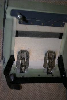 |
Sat 16 December 2006 | |
| Continuing with the clean up / finishing of the oil flap. Sanding back the 2oz and blending the edges. | 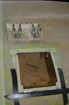 |
| The cowl edges were re-done also - everything seems to be sitting down well now. The cowl still needs a finishing layer of glass at some point. | 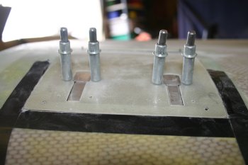 |
| This is the underside - shows the hartwell latches closed. Works well but I'll probably add a ~0.032" spacer between the latches and door to help the alignment a little. | 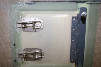 |
| Close up detail of the AL reinforcement plus single 2oz layer. The latch has made a nice 'seat' in the glass and locates well. | 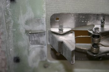 |
Wed 14 February 2007 | |
| We had significantly more EP filler mixed than we needed and rather than wasting it I decided to put a quick coat on the upper cowl surface that I spent time micro-ballooning / sanding way back when. Masked front and back edges (will probably need more glass work in these areas) and wiped down with acetone. | 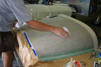 |
| Finished EP filler - looks REALLY good, some light pin holes on the lower edges, but the bulk of the surface is solid and without issue. I've been expecting the surfacing process to be exacting and today's result back up the principle - lots of effort in the micro-balloon process makes the priming look simple / easy. If the pre-work isn't done (like on the nose gear leg that I also tried) the pin holes show up really badly ;-). | 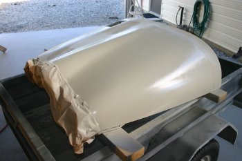 |
Fri 16 February 2007 | |
 | |
Mon 02 April 2007 | |
| One of the primary reasons for getting the prop back on was to test getting the lower cowl on and off. It doesn't! More cut outs in the nose leg fairing are going to be needed, but not something to rush into. | 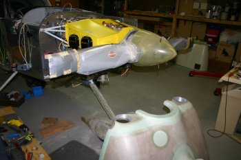 |
Tue 03 April 2007 | |
| Spent quite a bit of time working out the best way for getting the lower cowl on. It is very tight between the spinner and the cowl and requires more cut out on the nose leg location. Steady slow iterations needed. Finally got it to hook in - basically the nose goes in and up and then the rear edge comes up / over the fuselage and pops in... Easy when you know how! | 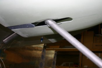 |
| Put the top cowl on to check various alignments - first time this has all been together with prop, spinner, engine and gear - nice to see it all working ok. Top clearance between spinner / cowl is about 3/16", bottom is 5/16" - should provide the space for the engine to drop a little if it is needs to. | 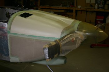 |
Thu 05 April 2007 | |
| Also built up the cowl hinge covers with micro - this can be taken down in situ tomorrow hopefully. | 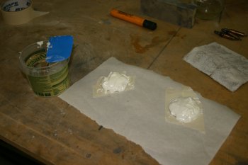 |
Fri 06 April 2007 | |
| After trimming / hacking about the covers, got the cowl halves together and screwed them in. Then more filing / profiling - might just work! | 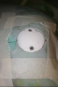 |
| Then more micro-balloons - this time a little thinner and did some skimming of the lower cowl and built up the edges - hopefully this should smooth a lot of the gaps that we have had until now - the only concern is getting the parts apart again.... |  |
| Dad went back to the spinner rear plates, starting with alignment and drilling of the rear plate. | 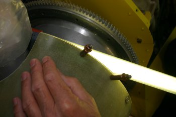 |
| Then more CAD developement and starting making plates. I got another reference file from the net which seems very close to my curves which is encouraging. At this point all we need is the parts to go together and not interfere with the prop - the clearance hole can be made later. | 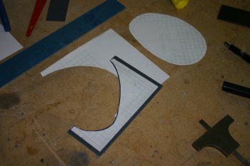 |
| Like most things - practice / experience makes tool choice easier - sabre saw works well for this type of tight curves - I remember when we started with this tool and it being a real handful.... | 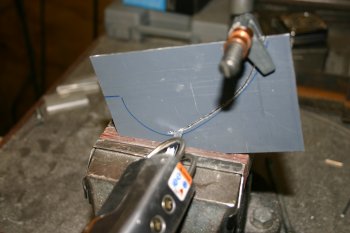 |
Sat 07 April 2007 | |
| I did some rough shaping / sanding of the cowl corners and the plugs look like they should work well. After the concern from yesterday the cowl halves actually split very well. I ran a knife down the break lines and the prized the parts apart - then just an edge that then just needed more tidying and sanding. Slow process but needed. | 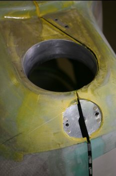 |
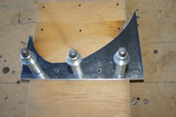
| Meanwhile Dad continued with the rear plates for the spinner. One of the challenges is getting the right location for the gap plate to meet up with the fibreglass spinner. | 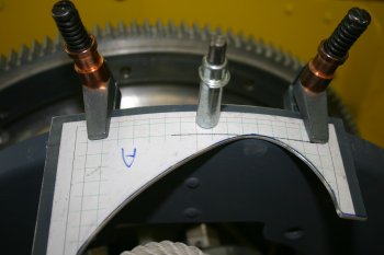 |
| A second attempt was made and seems to be more promising. | 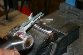 |
| Current state of play - next step is to mate the metal and spinner parts then the final clearance hole for the prop can be finished on the bench. | 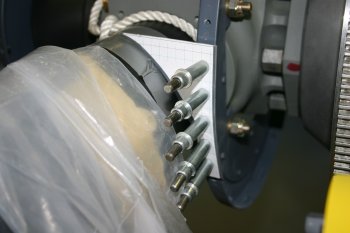 |
Sun 08 April 2007 | |
 | |
Wed 11 April 2007 | |
 | |
Thu 12 April 2007 | |
 | |
 | |
Mon 07 May 2007 | |
| Dad did a few bits on the spinner. | 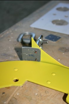 |
Tue 08 May 2007 | |
| Dad still trimming / sorting spinner. | 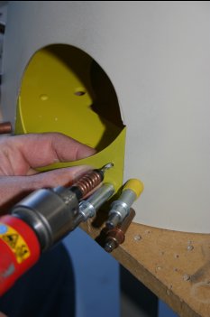 |
Wed 09 May 2007 | |
| This is the current plan for spinner cut out - Dad finished early as it was a convient place to stop and he is away for a week. | 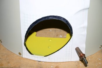 |
Mon 21 May 2007 | |
| Dad trimmed and shaped the spinner access holes - slow work but it does show in the end. We have about 3/8" to 1/4" gap around the prop root. | 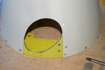 |
Sat 26 May 2007 | |
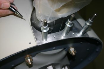
| Trimmed and worked on the cowl hinge pin cover locations - a basic solution now working, need more attention on the ends of the pins. | 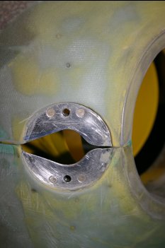 |
Thu 31 May 2007 | |
| Also think this might be a solution for the cowl to plenum transition. | 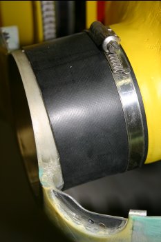 |
Wed 06 June 2007 | |
| I prep'd for fibreglass work - the oil dipstick door needs riveting. | 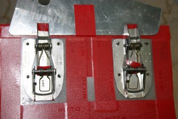 |
| I tried a layer of flox to provide additional support - but it just generated a big mess. Ended up cleaning and soaking the latches in acetone to undo it and recover the components. | 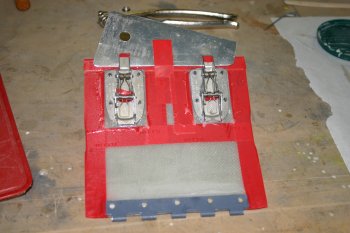 |
Sun 12 August 2007 | |
| New riveting of the oil cooler door latches. I made .063 spacer squares, combined with a spacer during riveting - this seems to provide a better alignment. | 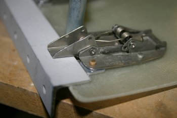 |
| Drilled and sorted nutplates on the oil door hinge and mounted it up. | 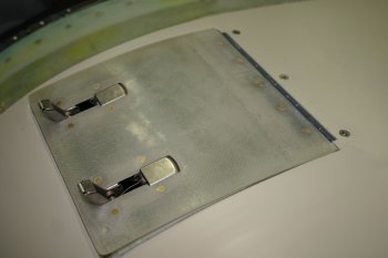 |
Mon 13 August 2007 | |
| Lots of sanding and first coat of microballoons on the LHS of the lower cowl. | 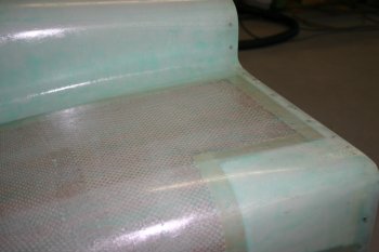 |
| Also filled and surfaced the oil door, hope I'll still be able to open it.... | 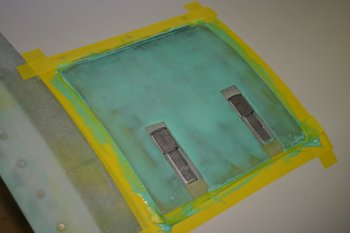 |
Wed 22 August 2007 | |
| Lots of cowl sanding - it seems to have made a good start at filling the pin-holes but is going to need another session at least. | 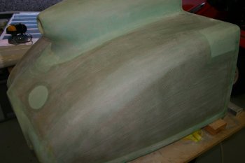 |
| The oil door at least came up pretty good first time. | 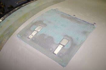 |
Wed 29 August 2007 | |
| Sanding / prepping and then more microballoons for the other side of the lower cowl. | 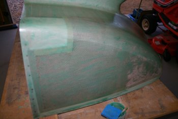 |
Thu 30 August 2007 | |
| More sanding work for the lower cowl - shame that I ran out of micro before the front corner.... |  |
Sat 01 September 2007 | |
| Cowl sanding..... boring! |  |
Thu 01 November 2007 | |
 | |
Thu 08 November 2007 | |
 | |
 | |
 | |
 | |
 | |
Fri 09 November 2007 | |
 | |
Wed 14 November 2007 | |
 | |
 | |
Thu 15 November 2007 | |
 | |
 | |
Sat 17 November 2007 | |
 | |
Sun 18 November 2007 | |
 | |
 | |
Fri 23 November 2007 | |
 | |
| Home | Carl Morgan | Previous|Next|Latest |