Fri 20 February 2004 |
| We started by finishing off the HS skins. Normal bucking routine. | 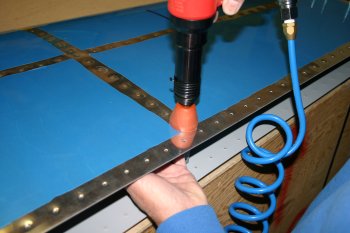
|
| The next step is the rear spar. We are currently waiting for some more rattle can primer which I need to fix a couple of things before the rear spar can be attached. | 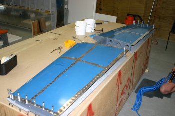
|
| Therefore, we hung up the HS for safe keeping and moved onto other things. Probably only a couple of hours to complete once we have the materials. | 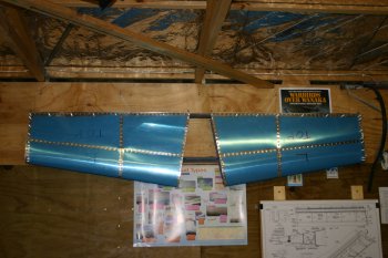
|
| The logistics of the project are one of our biggest challenges, partly being in the middle of New Zealand, partly seeming to have problems getting quotes / products out of NZ suppliers and partly just being a long way away from the US sources of aircraft parts. Currently things pending include - proseal, fuel valve, bolt hardware, electrical wiring components etc. These aren't all critical path but with shipping costs (~US $50 per order) I try and batch things as much as possible. | |
| Therefore we moved onto yet another new area - the undercarriage. | 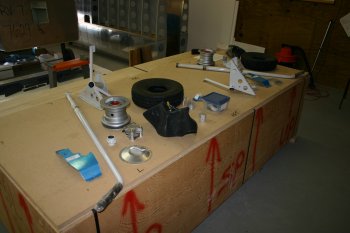
|
| Dad started work on the top part of the gear legs whilst I worked on the lower end. We also split things left leg for me, right for him. This is the weldment that has to go up against the spar for the main right leg. | 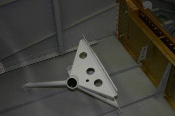
|
| Quite a bit of finishing work is needed on the powder coated parts to make them fit. Cleaning up the edges and carefully scotchbriting the ground parts to easy the fitting. | 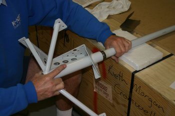
|
| Then match drilling of the parts. I was a bit nervous about this as the ground parts have really nice close tolerance fits on standard bolts but a drill does work - just follow the instructions (again)! | 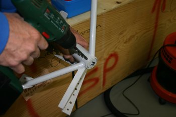
|
| The last piece of preparation for the hole cuts is to remove the temporary stand as this uses the spar for support and the gear legs need to take priority. A simple box / saw horse does the trick. Dad also worked on a template and is ready to go tomorrow morning. | 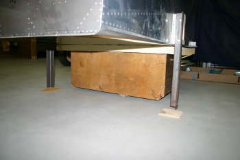
|
| I got stuck into the lower assembly. The first thing on the list was the brake bracket. This has to be opened up slightly for the powder coated mount. No easy / good way of doing this so I ended just using a scotchbrite wheel in the diegrinder and carefully checking things as I went. | 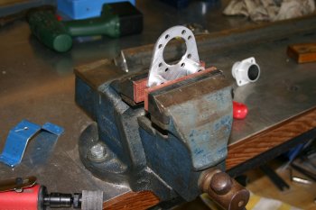
|
| Next up were the spacers. Yet again I miss not having the lathe running yet. I may come back and redo a lot of these 'properly' but the current results are probably fine and fit for purpose, we will see. | 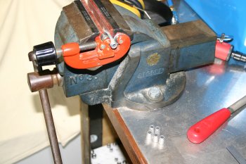
|
| This is the basic inner section of the wheel bearing (NOTE: The brake mount is on the WRONG way round in this photo). The plans are really poor for this area, a decent exploded ISO would make life SO much easier. The gear leg needed scotchbrite 'reducing' a little to get everything to fit. Hint: The close tolerance cross bolt is in bag 1068. | 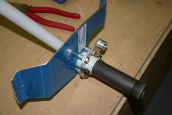
|
| Next up I started on the left wheel. First remove the three bolts and split the hub apart (a 'gentle' tap is needed). | 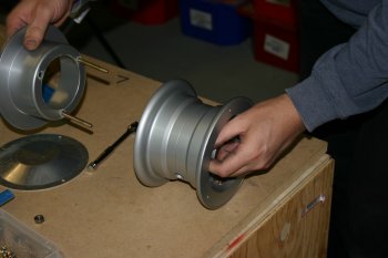
|
| Then apply talc to the inner of the tire for 'lubrication' and insert the tube and then outboard hub side. Don't thread the tube valve through the hub until after it is inside the tire - it doesn't work (don't ask me how I know!) | 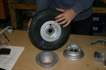
|
| The reverse side, ready for the inboard hub. A little air is in the tube at this point to help seating. | 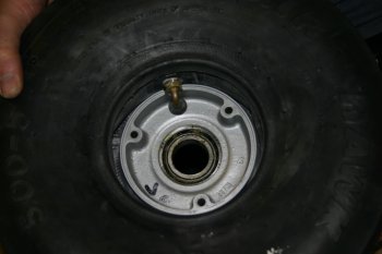
|
| The completed wheel assembly. The bolts torqued to about 90 ins-lbs and the pressure nice and low around 10 PSI for current working. Tomorrow I'll worry about fixing it to the axel! | 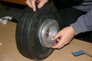
|


