Sat 28 February 2004 |
| We continued with the rudder assemble today. Dad focused on the mounting and I continued with the pedals. | 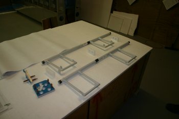
|
| First thing for me was to re-trim the 8 angle supports for the pedals. | 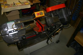
|
| The brake side plate needed some more edge clean up work, but with the radius of the corner being quite tight an improvised sanding tool was needed. | 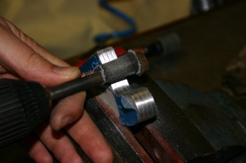
|
| Dad worked on the drilling of the plastic blocks. Note the end blocks are handed, the rudder tube is drilled in at a slight angle. | 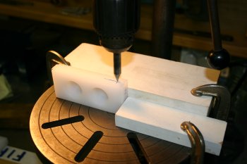
|
| The rough setup. Dad then moved onto the support bracket. | 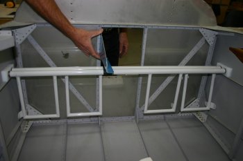
|
| We decided no to trim the support at all and provide the maximum flexibility for rudder adjustment, although I doubt we will need very much movement. A notch has to be cut for the firewall angle. | 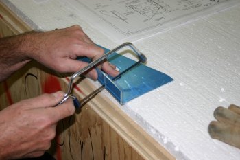
|
| Sabre saw for the longer cut and then some further trimming and filing. | 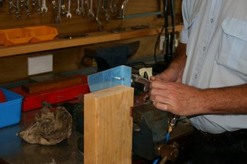
|
| I moved on to drilling the angle supports. I elected to pilot drill the lowest holes on both the aft and sides of the angle supports via a jig to give an repeatable and accurate hole. These were then opened to #30's for the pre-punched rudder pedals. | 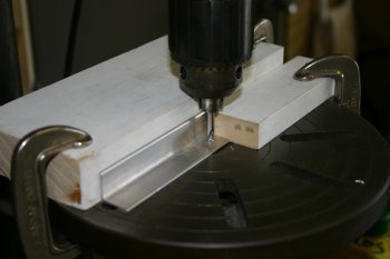
|
| Using the drilled locations the angle was clamped and the rest of the holes could be completed. Careful support for the angle (with the radiused internal corner) was needed. | 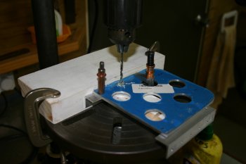
|
| The parts starting to look like pedals. I then marked up the trimming for the 'non-master cylinder' side angles. | 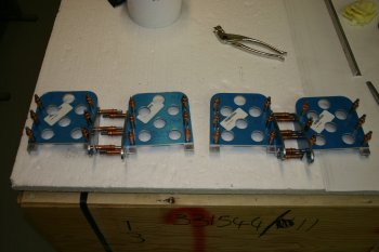
|
| I did the trimming in a two stage process, starting with a rough cut with the hand held rotary burr. | 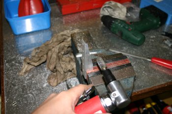
|
| And finishing with a burr in the pillar drill plus a 2 axis vice. I made a wooden wedge to set the angle for the final line. These can then be smoothed and finished. To be continued tomorrow. | 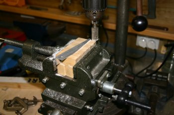
|


