Fri 02 September 2005 |
| Continuing with the baffles - the upper rear mount uses the engine crankcase bolts - more taking my finished engine apart! | 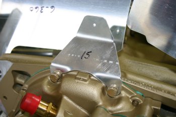
|
| The LHS rear baffle has a strange alignment. The plane that the bolt location is in is well aft (1/2") of the part 15 brace mount. Not quite sure of the process, may need to put a bend in. Some trimming needed but pretty good out of the box. | 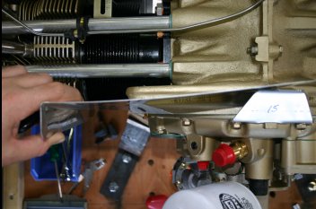
|
| The RHS rear baffle on the other hand, needs significant trimming and working. The good news is the plane of alignment between the rear surface and the #15 brace seems much better. | 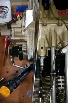
|
| Lots of trimming by file, rotor burr and scotch brite wheel. Not difficult just taking it slowly and carefully to try and reduce any excessive trimming. | 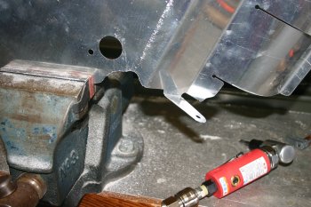
|
| Photo of the front looking back on the RHS rear baffle. | 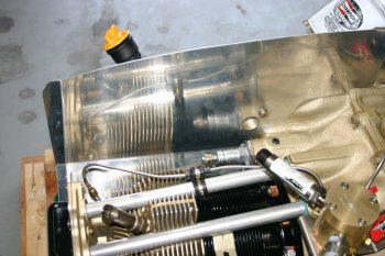
|
| The problem with the RHS rear baffle to RHS aft cylinder baffle (parts #7 & #8) is the gap. Not sure of the 'best' solution - looking at some of the other guys websites, cutting the flange off and using a piece of AL angle. More thought needed and probably no decisions until the engine is on the aircraft and a lower cowl is roughed in. | 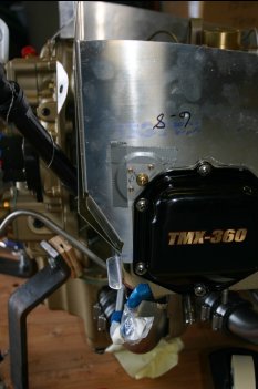
|
| Then onto the front baffles. The LHS uses the cylinder mount point (right of photo, half way up) which provides the top fixing of the angle stiffener. | 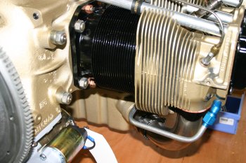
|
| The stiffener is based from a .063 angle, the shaping was fairly easy, just requires time and effort. | 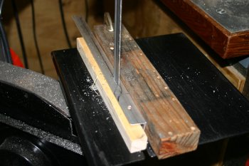
|
| This is the underside of the LHS baffle. Note the part #13 (with the blue plastic on). I didn't understand the original layout - this will get a piece of angle at the top to support the lower surface of the baffle floor. | 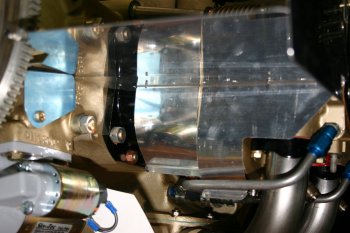
|
| The 'finished' support for the LHS baffle floor. In general so far the baffles haven't been too bad, just slow steady process. | 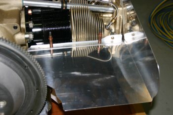
|


