Wed 21 September 2005 |
| More continuing work on the joining of the lower and upper cowl. Slow iterative process. | 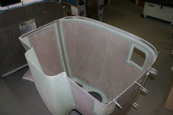
|
| Then it was rechecked on the fuselage. It is getting progressively easier to put on and off the cowls. The top half in particular seems to need a sequence - front, side and rear. | 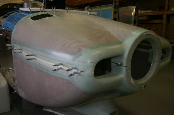
|
| The front join also has the pin which will need retaining in some way. I quite like the method that Walter has used - detail entries here. But mainly I'm not going to do much more until we have the propellor (later Oct at the earliest) and can confirm all the distances. | 
|
| The rest of the afternoon was back with the FADEC harnesses / layout thinking. Having the engine off the fuse makes some of this much easier. | 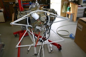
|
| Dad worked through the spark plug cables and organised them all as labelled (1 to 4, Top & Bottom). | 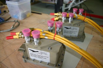
|
| It became obvious pretty quickly the implied location from the spark plug leads was not going to work - right in front of the prop governor control cable. I'm pretty sure the lead lengths have come from Ken Barto's installation - but I think he had a fixed pitch prop (or at least a different governor / control combination). | 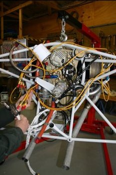
|
| I continued to look at cable lengths (fuel pressure senders and throttle body sensors)
plus possible locations for the battery boxes and ECUs.
There is very little guidance on a suitable standard configuration at this point for a dual battery,
FADEC system for an RV7. Everybody seems to work on the basis - the firewall is large, just put our 'bit' here,
there seems to be little thought for how everthing goes together overall.
I know we are 'experimental' builders and I'm happy to work things out -
but when a 'standard' configuration is shipped it would be nice to have something that could work. I suspect things have evolved and some of the cabling hasn't been updated / tested recently. Maybe I'm being picky - but it seems a shame that a really good technicaly solution is being let down by the last 5% with the packaging, documentation etc. | 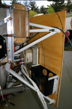
|
| This is some possible thoughts for the RHS, I want to get the ECUs and Batteries as low as possible on the firewall but also balanced between the left and right sides. More emails with the USA guys - hopefully we can come up with a good solution with them and others in the future won't have to go through all the same pain yet again. | 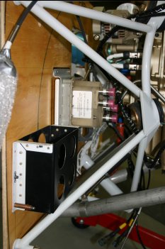
|


