Wed 11 January 2006 |
| To assist with the other tasks, we started by de-rigging the empennage. | 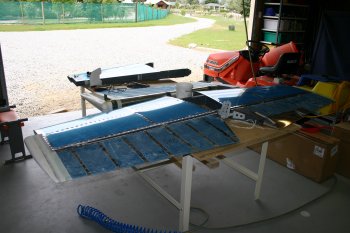
|
| I went back to the VOR antenna mount, after more thought I decided it wasn't right (the forward fold was about 1/16" out) so I modified the CAD drawing and made a second mount. The CAD drawing system works well, it provides a good way of 'tweaking' designs, then it is just trying to get the two folds accurately to the marks. | 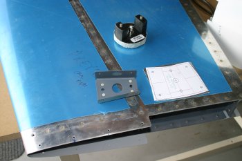
|
| The second time worked like a charm, then it was deburring, dimpling and fibreglass shaping. Then final solution seems to have come out really well, I'll wait until the VS is mounted back on the fuselage to be sure. I'll probably need to make a backing strip for the nutplates and I also added a second pair of screw locations. | 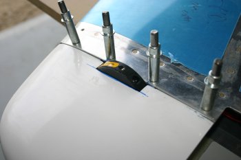
|
| For most of the afternoon, I continued with the sanding of the rudder tip. Starting with 100 grit paper on the palm sander, | 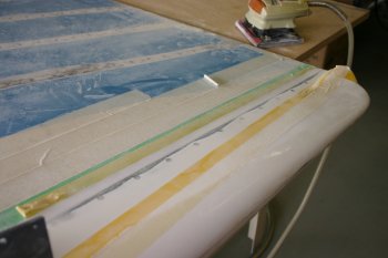
|
| then removing the protective electrical tape and going down to 150 grit. This provided a nice blended edge to the micro-balloon filler. | 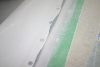
|
| Dad continued with the empennage fairings. | 
|
| The rivets were drilled out no problems. | 
|
| With the VS off the fuse, and the HS back on, the fibreglass fairing actually fitted better than we expected. At this point only two forward locations were fixed. | 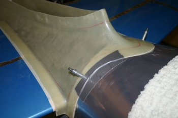
|
| Then continuing with the lower metal covers, we were concerned that the pre-punched parts seemed very 'high' compared with the HS skins so some re-checking was in order, but in the end we decided no problems with the HS mounting and to just use lots of small amounts of trimming were needed. Using the bending brake for support filing was fairly easy. | 
|
| The end result for the LHS - currently we are going for a 1/32" gap and trying to do without the rubber seal - we can always increase the gaps if needed later. | 
|


