Wed 04 October 2006 |
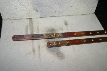
| I added a couple of studs to the circuit breaker bus bars and soldered them in and then continued with wiring and clamping various wire runs. | 
|
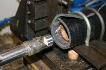
| Dad sorted the two stick grips. Although there is only a single photo, it has probably taken best part of 2 days effort to come up with solutions / tools to drill the large bore holes acurately to the right size. Do yourself a favour and order the right sizes to start with - P1 = 1", P2 = 7/8". | 
|
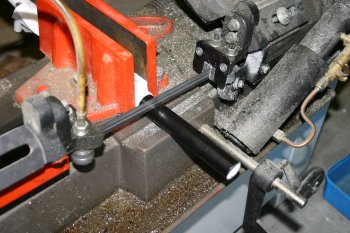
| With the new grips - the sitcks were marked and trimmed to clear the lower cross bar. About 5" of P1 (probably 1/4 - 1/2" more than needed) and about 3" of P2 stick. | 
|
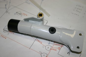
| Dad also sorted the P2 stick penetration for the control lines. P1 on the list for tomorrow. | 
|


