Mon 16 October 2006 |
| Dad completed two UHMW supports for the Hall Effect 'donuts' - these provide the AMP measurement points without the need to have a shunt in the line. | 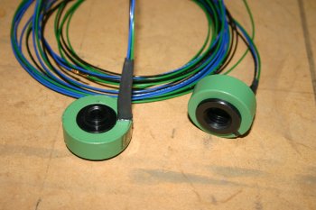
|
| I then got the main panel out and mounted up the GRT MFD screens. | 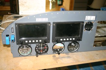
|
| This enabled the start of a cable harness for the GRT components - a large chunk of the afternoon was taken with documentation / planning / organising. This is the back of MFD1 and 2 with the ARINC module in MFD1 (RHS in photo) | 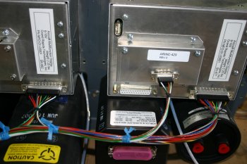
|
| Then onto to avionics stack - I mounted the freshly painted side rails and hopefully installed the rack for the final time. | 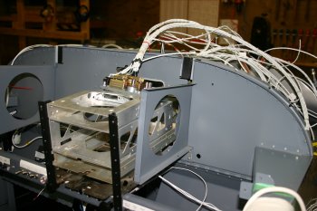
|
| The mounting of the rear plates of the avionics was a bit of bear - very tight / fiddly work. | 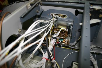
|
| A 'current' panel photo - just for the hell of it. Begining to look right - some more thoughts on USB and music jack locations. | 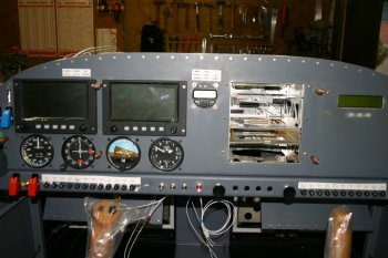
|


