Mon 18 June 2007 |
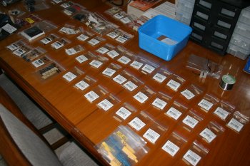
| I got a selection of resistors and bits for stock. | 
|
| I decided a temperature control soldering iron was needed - so another chance to buy more tools..... | 
|
| Then onto the 3x3 LED board - a few extra photos, one for each of the steps. | 
|
| Top and bottom accete masks. | 
|
| Attached to glass plate. The actual laser 'soot' is on the bottom surface and therefore in contact with the PCB board. | 
|
| Expose to light (UV I think is the important bit) - normally for about 14 mins, repeat on second side. | 
|
| Develop the mask - the white spacers are to help prevent scratching of the lower surface. | 
|
| Etch in ferric chloride for ~15 mins and you get a base board | 
|
| Then lots of drilling, mixture of .6mm, .75mm and #60 and #57 used for the components, #33 for the mounting locations. Via's soldered first, then the DIL sockets. | 
|
| Finished board ready for LEDs - Forward surface / back of board) | 
|
| Aft surface / front of board. | 
|
| Then 4 spacers, #4 thread through the center and parted to the right length to keep the LEDs up tight against the plexi-glass surface. | 
|


