Electrical & Avionics |
| Generally speaking this is being left until as late as possible. The electrical priniciples will be based on AeroElectric Dual Alt / Dual Battery design. More details to follow. | |
|
| Other things today included finalising the Stein electrics order, hopefully we have got something close to what we need, all takes time however. | |
|
| Dad did a number of 'bits' but started seriously looking at the ground straps for the FADEC / batteries. Looks like we were short shipped 2 long grounding braids from AeroSance - but shouldn't be a biggy. | 
|
|
| I had a slow / gentle day doing other bits, sorted a 12V DC power supply (8Amp) that I got a couple of weeks ago. I boxed it up added a fuse and a couple switches. Workes nicely... | 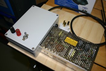
|
|
| Spent a few hours doing electrical design work for the flaps and trim controls. Also got the HallEffect sensors running on the GRT EIS4000. The Aux4 input seems to be having problems - not sure why yet - hope I don't have a dodgy EIS. | |
|
| It was a cold day outside and I wasn't in the mood for freezing in the shed. Therefore we ajourned to infront of the fire and continued with planning for the electrical systems. Lots of things at the moment are going slowly in actual progress, but lots of thought time. Hopefully this will keep the mistakes / dead ends to a minimum. | |
|
| After yesterday's thinking time, the plan for the electrical ground layout seems to be coming together. We are currently planning on a chunky location on the rear of the firewall (that was today's fabrication) and probably a 'rear' earthing location for the Nav lights, Strobe pack and flap motor. | 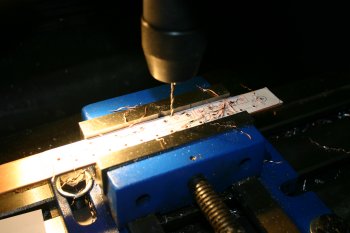
|
|
| Dad went shopping and got a large crimper - this will be used for the > AWG 10 cables on (mainly) firewall forward. | 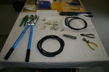
|
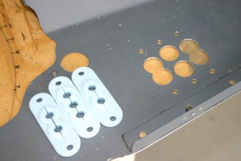
| I made the main aft side grounding block drilling and soldered a couple of forest of tabs sets. | 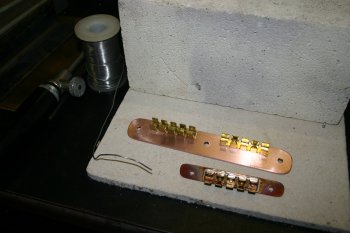
|
| I just used standard soft solder, plus blow lamp, the screws were then trimmed and cleaned up on the back surface | 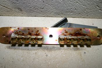
|
|
| I was busy with other things, but Dad sorted the mounting for the centralised grounding straps. | 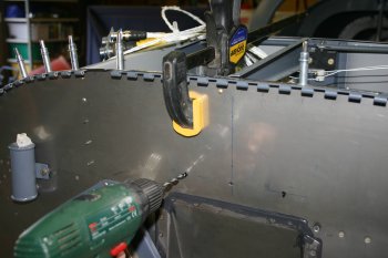
|
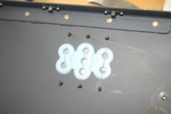
| The outboard bolts will have the engine grounds / battery grounds attached. We have also got a small set of tabs on the forward side, although we probably won't need that many. | 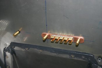
|
| And on the aft side, three bolt locations, the outer points will go to the FADEC harness and the mid bolt will go to the mid-ships ground point. | 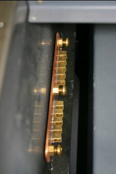
|
|
| Next is some of the heavy guage cables. | 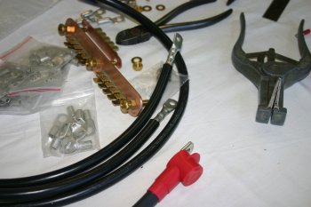
|
| The battery terminals also needed a set in them to help with the routing. | 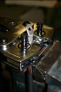
|
|
| After much thought, ideas and bad options - this is where the main and secondary alternator feed circuit breakers are going. I'm still not convinced one way or the other on the merits of CB for the feed (vs. ANL on the firewall forward) but this seems to be the more 'common' method in NZ and a safe option. | 
|
|
| I also sorted a mini forest of tabs for the mid-ship ground point. It will provide a single GND for both the wings (landing / taxi / nav lights) plus central fuselage components (strobe pack, trim control etc). | 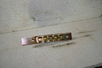
|
|
| Short day - more thinking and planning. Also sorted the B always hot bus fuse block mounting - I need to get some longer #8 screws for here. | 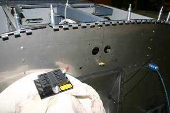
|
|
| I also made a mini ground bar for the mid-ship location. We are problably going for over kill, but everything is getting its own ground connection (ie. no using the airframe as a ground) and this will provide the strobe, wing lights, nav lights and misc control ground connections for the mid fuselage. | 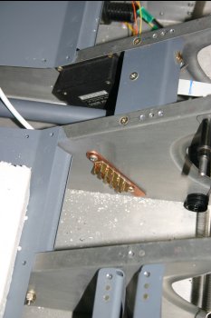
|
|
| I installed the new A/H - a little difficult with the fibre-lite ring and I ended up using both the supplied spacers. Also spent a bit more time on the annunicator layout / design problems. | 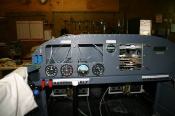
|
|
| Slow progress with the wiring - main A fuseblocks wired up. | 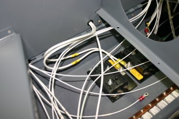
|
|
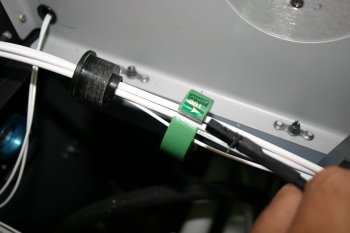
| I added a couple of studs to the circuit breaker bus bars and soldered them in and then continued with wiring and clamping various wire runs. | 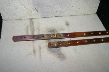
|
|
| The third iteration of the idea / bracket. Looks promising need to wait to work the cables / check final fitting. | 
|
|
| Dad completed two UHMW supports for the Hall Effect 'donuts' - these provide the AMP measurement points without the need to have a shunt in the line. | 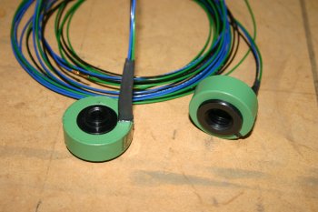
|
|
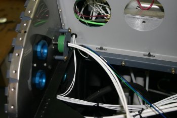
| Dad wrapped up some firewall forward routing / clamping. | 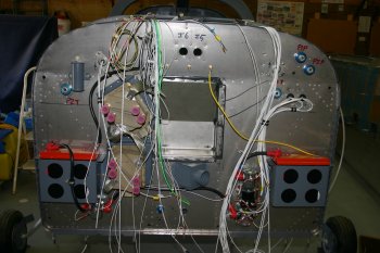
|
|
| Dad worked on the avionics ground strap. We will have two tab straps and a DB9 connector in the middle, it is amazing how quickly we are using up the ground locations. | 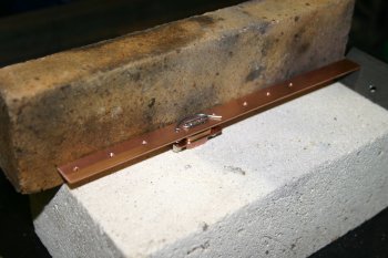
|
|
| The finished avionics ground strap, this was then coupled directly to the firewall ground strap. | 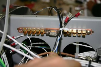
|
|
| The majority of the day was spent working with the Hall Effect sensors. The default Scale & Offset factors (186 & 357) seems to be way out. By taking a known current source (a landing light in this case = 6.4 amps) and measuring the volt output a better understanding can be gained - and calibrartion. | 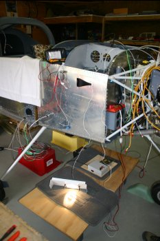
|
| The 'measured' amps is then multipled up by passing the lead through multiple times.
One of the first observations is the B side is linear upto and including the 13 passes (84amps) but the A side gets saturated at about 60amps.
I not sure if this is just manufacturing variation or a 'bad' sensor - to my mind it is well outside manufacturing tollerances.
A table was then made for the measured values and I used Excel to goal seek the best fit number for the scale factor and then calculated the offset last.
I also found the EIS can take 'big' offset and factor numbers, if you multiple up the SF / SO by 10 decimal values can then be used. My test results are below:
Turns	AMP	A Volts	Book A	Cal A	B Volts	Book B	Cal B
0	0	2.39	-1	0.4	2.39	0	0.4
1	6.4	2.62	17	6.8	2.49	7	6.8
2	12.8	2.85	34	13.3	2.59	15	13.2
3	19.2	3.08	51	19.7	2.69	22	19.6
4	25.6	3.32	69	26.1	2.79	30	26.0
5	32	3.55	86	32.5	2.89	37	32.6
6	38.4	3.80	105	39.4	2.99	45	38.9
7	44.8	4.02	121	45.4	3.09	52	45.5
8	51.2	4.23	137	51.2	3.19	59	51.6
9	57.6	4.49	156	58.4	3.29	67	58.0
10	64	4.72	173	64.7	3.39	74	64.3
11	70.4	4.74	175	65.2	3.49	81	70.6
12	76.8	4.74	175	65.2	3.59	89	77.2
13	83.2	4.74	175	65.2	3.69	97	83.7

Factor			186	688		186	1602
EIS Offset		357	1305		357	3057
Offset			-179	-652		-179	-1528
For reference the equation is: Result = (Value * ScaleFactor / 2.5) + ScaleOffset
So we have 'an option' but the A side is still a concern. | 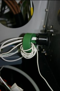
|
|
| I removed the left tray and drilled / fixed the WingWag and fuel pump relay. | 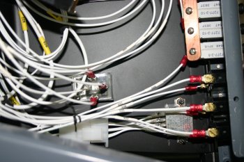
|
| I've been trying to sort locations for all the electronics boards, I was hoping the right hand tray would be big enough but not so. The new plan is to mount the dimmer controls on the LHS behind the MFDs. | 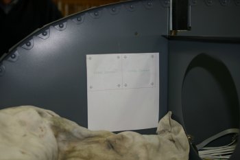
|
| Then after some testing / learning, power and ground cabling. We were going to use a seperate switch control for the dimmers, but the minimum load is only about 30mA so I've decided to just tag the dimmers onto the nav lights switch. | 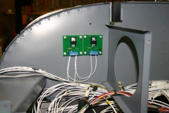
|
|
| Dad did some tidying up of electrical stuff and mounted the hall effect sensor - works well after all the effort / thought. | 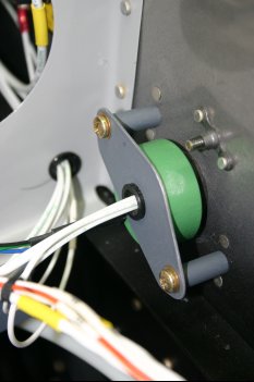
|
|
| Sorted the CB boots for the 40 and 60 amp alternator feeds. Also remounted them with new shakeproof washers. | 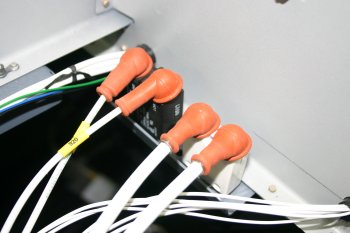
|
|
| | 
|
|
| | 
|
| | 
|
|
| | 
|
|
| | 
|
| | 
|
|
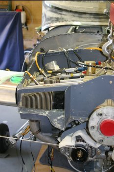
| Also positioned and connected the primary alternator. | 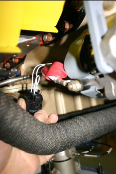
|
|
| Sorted the firewall Oil Temp / Pressure connection. | 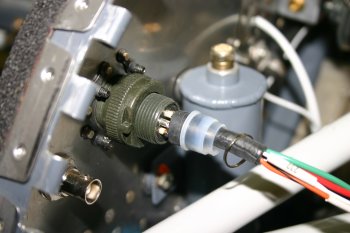
|
|
| An additional fuse / supply added for the EDU logging unit. This is the B bus mini fuse set. | 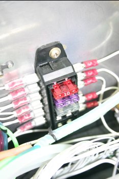
|
|
| I reworked the ground return from the pitot heat and added the read relay switch. This will sense current going through the pitot heat, rather than just the fact that power is being switched. | 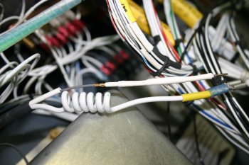
|
|
| Pitot reed relay finished and tested - works well. | 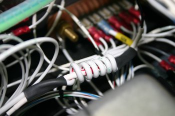
|


