Engine Build 1 |
|
| This is the main Mattituck assembly workshop - multiple work stations with a crane runner along the ceiling to enable the engines to be moved out ready for shipping / spraying. All very professional and shows that they have been doing this for a while! To the left of the photo is the same area again working on Mags and sub-assemblies for accessories. | 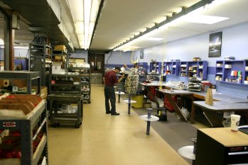
|
| John had done a bit of preparation the day before I arrived and had all the part laid out for our new engine. Here is the main work area - crank shaft and 'small stuff' - nuts, tappets etc | 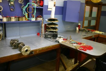
|
| This is the core of the engine - the crankshaft. We will be having a constant speed propellor and you can just see the 'inlet' to the hollow crank on the forward bearing surface. | 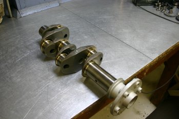
|
| This was the stack of 'bigger stuff' - pistons, induction tubes, sumps etc. | 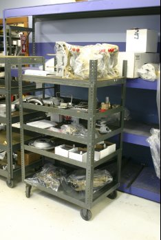
|
| And the four cylinders - just under 1.5 litres EACH - it will be a 5.9 ish litre engine by the time it is finished with a max rated 180HP at sea level. These had also been balanced and port flow matched before I got there. | 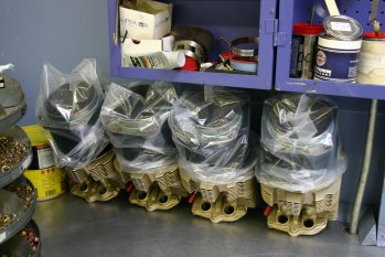
|
| First step with the crank was to get the seal on. After the normal - "ask the niave punter" how to get a small band over a large disk - the solution is a custom tool which makes it very easy. One of a number of examples of where even with a full engine kit - building it still requires a set of specialist tools / techniques. | 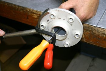
|
| The simple 'net' result. | 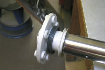
|
| The con-rods connect around the crank shaft - these had been tollerance checked and matched. | 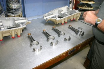
|
| The crankshaft is mounted 'nose down' on the stand and the build is underway. Oil is used to pre-lube the crank but then left for the surface tension to provide a glass smooth film before attaching the con-rods. This also allows for checking of hairs / debris before the bearing surfaces are mated. | 
|
| Then it is onto the crank case, left and right. | 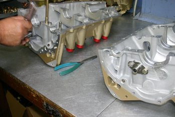
|
| This is the RHS and you can see some of the 'extras' the ECI case has, particually the O ring seals around the through bolts. Other minor modifications have also been completed compared with a 'standard' Lycoming engine for things like cam lobe pressure jets extra. Seems like ECI have taken the basic solution and done the obvious developments that Lycoming can't do due to the cost of re-certifiying. We don't have to worry about that particular problem and I think are probably better off for it. | 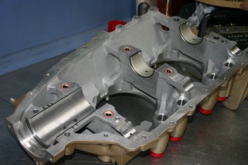
|
| Cam shaft setup, including the 'tach drive'. | 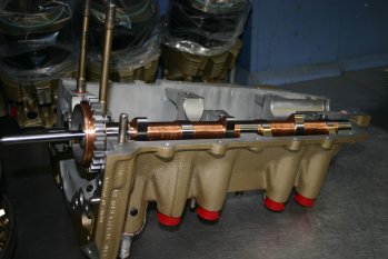
|
| The two halves with the crank bearings ready. | 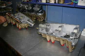
|
| Then the silk thread was put around the edge of the crank case. John used two independant threads which helps provide a belt and braces approach in case one leaks slightly due to a casting nick. Quite a bit of care on the routing was taken to minimise leak risks. | 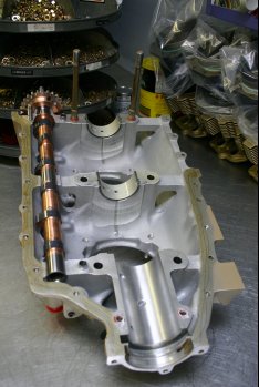
|
| Start of preparation on the accessory housing. This is just before the oil pump is put into place (centre right of photo). | 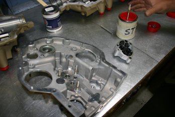
|
| When another builder / inspector was ready the case was mounted. | 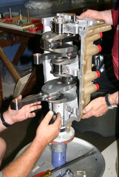
|
| One of the checks completed was the forward bearing play (I've forgoten the formal name) - basically the crank should move up and down slightly but not too much. | 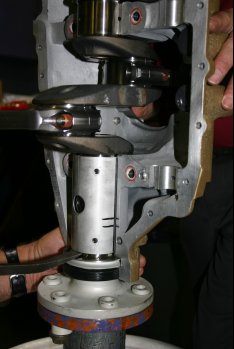
|
| Then second half fits snuggly on. | 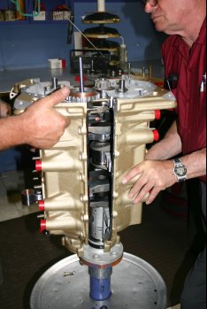
|
| The crankcase bolts can then be finger tight. This is the lower side where the oil sump and induction tubes go. | 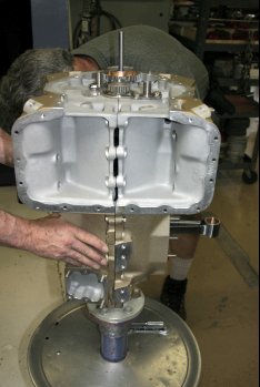
|
| Continuing with the accessory case - the locations clockwise from the top - RHS 'magneto' , Prop governor, engine fuel pump, LHS 'magneto', Oil filter. | 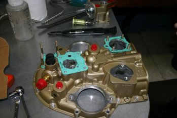
|
| Here you can see the oil filter adapter that TMX engines come with as standard that makes getting to the oil filter a lot easy - rather than point directly aft wards, it points up and to the LHS of the engine. Also installed in the FADEC speed sensor in the RHS mag location and the LHS has been blanked off. | 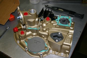
|
| This is the gear drive that provides power to the accessory pad (commonly used for the vacuum pump) but will have a second alternator on in our design. | 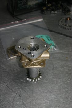
|
| Vernatherm installed which controls the flow of cold / hot oil to the filter. | 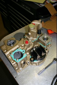
|
| Through bolts installed with a precision hammer. A reasonable 'tap' needed but careful to not go too far. | 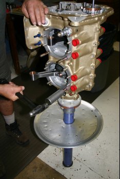
|
| Temporary spacers and nuts were used on the cylinder bolts to pull the halves together. | 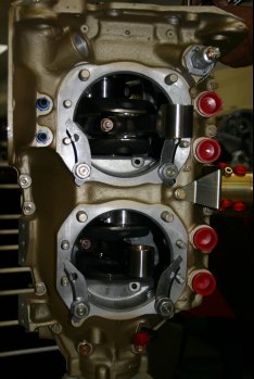
|
| The crank case nuts within the sump are safety tied together for safety - this area isn't accessible once the engine is complete and oil with added 'nuts' is not a good thing! | 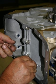
|
| Then the gear sections can be started. The crank, cam, mags, aux pad all have inter-linked gears which provide all the timing and drive functions. (Crank is the small one, cam is the larger one being worked on). All the bolts have lock tabs under them which are bent up to prevent them coming undone. | 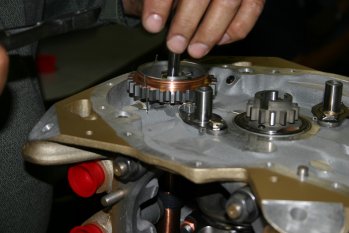
|
| The FADEC system uses hall effect sensors to detect the 'holes' in the timing cog on the right of the photo. Obviously the top dead centre needs to be in the right place - hence the red marks. | 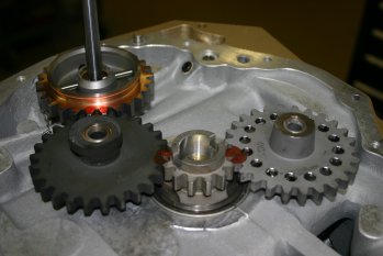
|
| Oil sump had a finger screen as it goes into the oil pump. This is a checkable item during servicing but not normally a big problem. The oil filter catches all the 'non-good stuff'. | 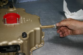
|
| The sump has a traditional gasket that can go on multiple (wrong) ways, however the new layout on the ECI sumps means it is much easier to get it right. | 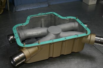
|
| The forward side view of the accessor case. Aux drive top left, governor drive bottom left, FADEC speed sensor (SSA) mid left and oil pump in the middle. | 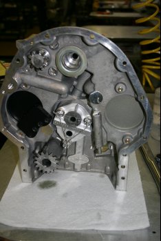
|
| A close up of the FADEC SSA and saftey tied oil pump. | 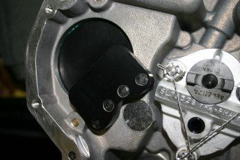
|
| The engine ready for sump and accessor case mating - this is just before a check point where an inspector comes and checks everything visually to make sure nothing has been missed. The blue tube is a sealant used with the gaskets. | 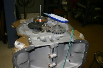
|
| The key to making a pile of bits into an engine - an experienced builder - this is John - great guy. Thanks for your time and patience explaining things to me - it really made the trip worth while. | 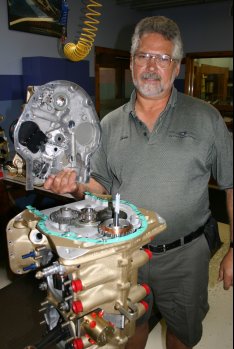
|
| Now it is starting to look a bit more like a Lycoming style engine! The red bits are caps used to stop dirt / dust getting into places that we don't want it. | 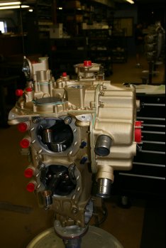
|
| Oil governor pipe feed to the front of the engine is installed - this is a stainless steel pipe and steel fittings. I understand there was an AD a while back making this the norm now. | 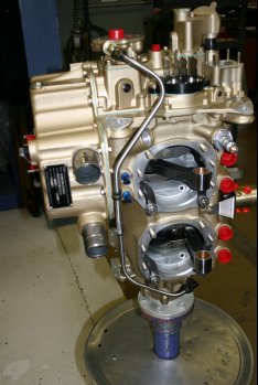
|
| Oil pressure control stack. Basically unwind for less presure, do up for more..... | 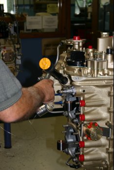
|
| This is the engine mechnical fuel pump. There is a small cam that is driven from the gears that drives a push rod up and down the moves this lever up and down that works the diaphram in the pump (or that is how I think it works!) | 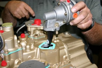
|
| The fuel pump is held in by allen key bolts which are then safety tied. Not sure why allen key bolts rather than drilled head bolts but may simply have to do with access. | 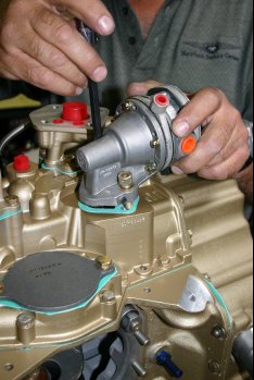
|
| SkyTec starter is installed - seems amazingly small to me and I'm told will spin the engine over really nicely. | 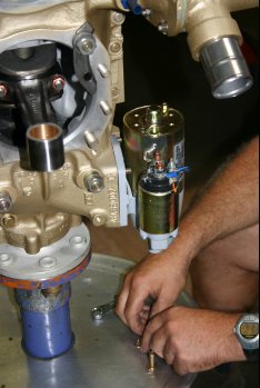
|
| Then it is onto the cylinders & pistons. These had all already been matched and numbered to provide the best static balancing. | 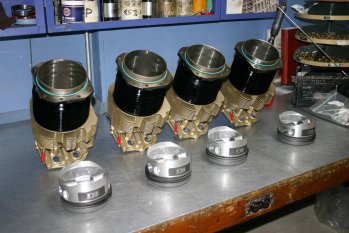
|
| The inside of a cylinder - the larger valve on the left is the exhaust - the right the inlet. Top and bottom are the spark plug locations. | 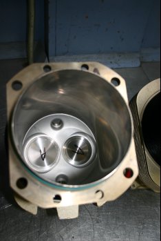
|
| The 4 cylinders with pistons and pins. The pins / supports had been specifically checked - I understand this is one area that tollerances can be rather tight and as the engine gets hot there is a risk of the pin seizing at the bearing surface. | 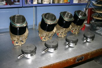
|
| These are the hydralic tappets getting pre-oiled. | 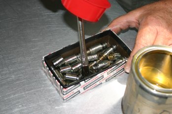
|
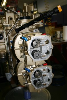
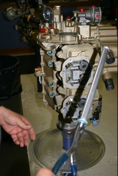
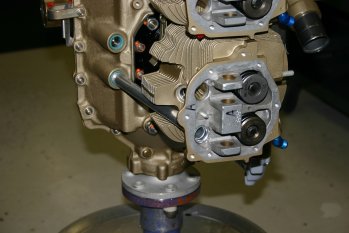
| Then it is assembling the pistons / cylinders, each of the 3 O-rings were offset. I'm sure they will move but to start with it probably helps sealing. | 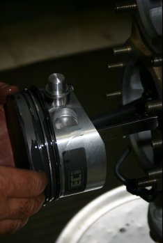
|
| The clever sleeve makes the cylinder alingment much easier. | 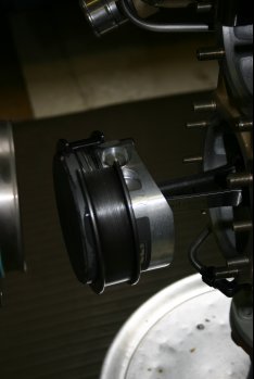
|
| Slide | 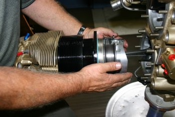
|
| Remove collar | 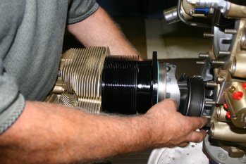
|
| And bolt down. | 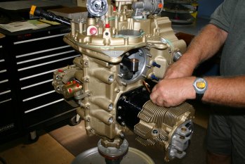
|
| Repeat - times 3. | 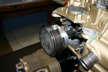
|
| | 
|
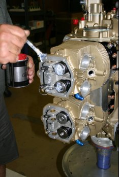
| Then all the cylinder nuts are torqued up (and torque sealed), this is another independant check point. | 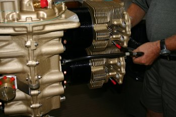
|
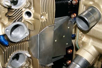
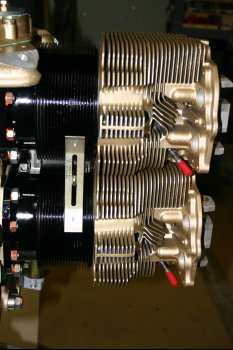
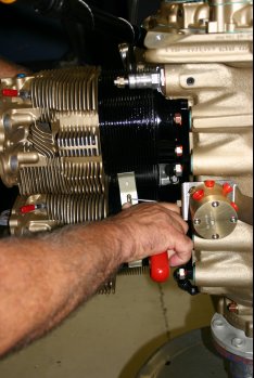
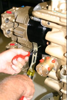
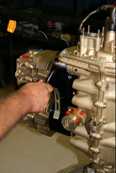
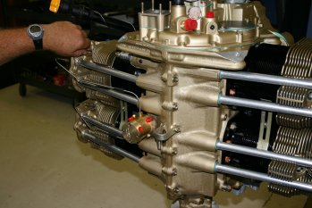
| Continuing with the inter-cylinder baffles and push rod tubes. These were one of the few parts that weren't painted. | 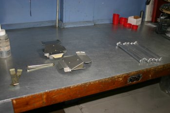
|
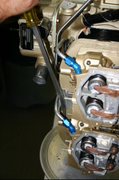
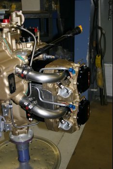
| Also cracked open the AeroSance box of goodies. This includes the high / low voltage harnesses and the fuel lines. However we were missing #2 fuel line, so a call was put in to AeroSance for an overnight delivery. | 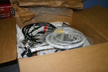
|
| | 
|
| | 
|
| | 
|
| | 
|
| | 
|
| | 
|
| | 
|
| | 
|
| | 
|
| | 
|
| | 
|
| | 
|
| | 
|
| | 
|
| | 
|
| | 
|
| | 
|


