


 |
 |
 |
| Home | Research | Delivery | Empennage | Wings | Fuselage | Finish | Engine | Electrical | GRTDecode | Previous|Next|Latest |
| Engine | Firewall Forward | Engine Build 1 | Engine Build 2 | FADEC | Baffles | Plenum | Cowling | |
FADEC | |
| As there seems to be little information on the 'net about the FADEC system and installations, I will try to provide more details than usual in case it is useful for someone else, if you have any questions drop me a line and I'll try and help. | |
Wed 31 August 2005 | |
| The FADEC ECU's are mounted on the firewall with these bases. As supplied there are a lot of rough edges / corners - so it was the normal file / debur / scotchbrite process. | 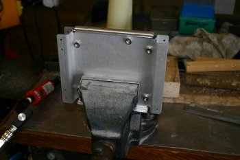 |
| Then I started unpacking some of the firewall parts. These are the low voltage harnesses from the FADEC system. | 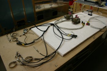 |
| Click for large image version This part of the harness is the low voltage part that is 'attached' to the physical engine. Each cylinder has EGT & CHT probes plus a solenoid to control the fuel pulse injection. The standard throttle body is replaced with a 'tube' that has a single butterfly valve plus a poteniometer and microswitch. This also provides a mount for the two independent ECU manifold air pressure and tempature sensors. | 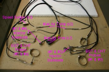 |
| Click for large image version The sensors above go into the main connectors which in turn go to either the firewall bulkhead connections or directly to the ECUs. The ECUs have an upper section which provides the high voltage 'spark' and a lower section with the 'inteligence'. Each ECU looks after two opposite cylinders. | 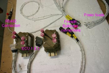 |
| Click for large image version The cabin harness provides the feedback / control systems. One thing I hadn't realised (but makes sense now) is all the power / ground supplies come through the firewall connector along with the other 'signal' information. The Serial Convertor (top left) provides a RS422 feed that will be converted and go to the EIS / EFIS system (yet to be ordered). Also there is a RS232 output that can be used with a PC program to record / monitor the engine during testing / use. The 'mag' control works the same as a traditional system - ground for 'off'. The fuel pump is controlled by a 3-way switch ON-OFF-AUTO, the FADEC system feeds the AUTO position and monitors for low RPM (<1000) and low pressure from the engine pump. The Health Status Annuciator (HSA) comes in two different versions - I went with the newer option which has just 2 LEDs (warning & critical). | 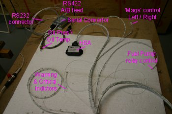 |
Thu 08 September 2005 | |
| Then we started looking again at the FADEC harness. Current thinking is to put the ECU's low and in the outboard corners - one each side. It appears the only really tight issue could be the fuel presure sensors (which connect to the spider) - more investigation needed. |  |
Fri 09 September 2005 | |
| I also re-visited the FADEC harness challenges. | 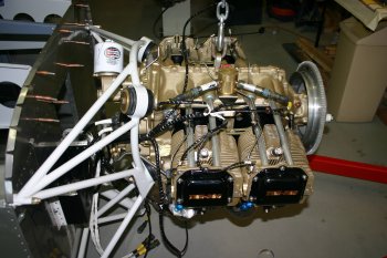 |
| The major problem is the Fuel pressure sensor cables. They are very tight and restrict all the other components. I think probably the harness will need spliting. | 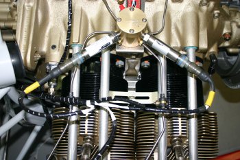 |
| The lower section is fine - Manifold pressure and temp sensors are fine. The top of the FAB does look very low. The cowl is needed for a number of alignment things, I think that might be a 'soon' job. | 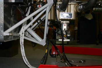 |
Thu 15 September 2005 | |
| The remaining time was spent working on the FADEC harness again. The summary is the default harness doesn't fit! The two areas that seem to be a major problem are: | 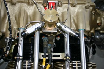 |
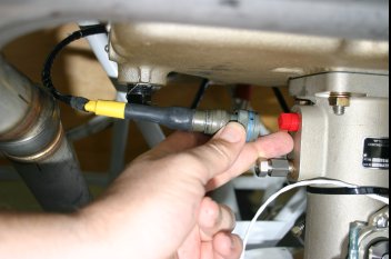 | |
I'll talk to Mattituck and see if they have have suggestions - primarilly thought - if you want to order a FADEC solution, you might want to get longer leads for the fuel and MAP pressure and temp sensors. Hopefully I'll be able to give more specific recommendations later. | 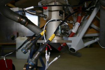 |
Wed 21 September 2005 | |
| The rest of the afternoon was back with the FADEC harnesses / layout thinking. Having the engine off the fuse makes some of this much easier. | 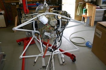 |
| Dad worked through the spark plug cables and organised them all as labelled (1 to 4, Top & Bottom). | 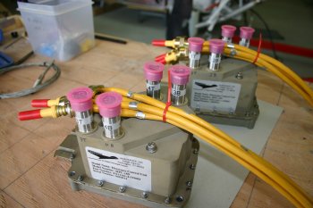 |
| It became obvious pretty quickly the implied location from the spark plug leads was not going to work - right in front of the prop governor control cable. I'm pretty sure the lead lengths have come from Ken Barto's installation - but I think he had a fixed pitch prop (or at least a different governor / control combination). | 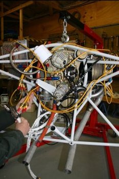 |
| I continued to look at cable lengths (fuel pressure senders and throttle body sensors) plus possible locations for the battery boxes and ECUs. There is very little guidance on a suitable standard configuration at this point for a dual battery, FADEC system for an RV7. Everybody seems to work on the basis - the firewall is large, just put our 'bit' here, there seems to be little thought for how everthing goes together overall. I know we are 'experimental' builders and I'm happy to work things out - but when a 'standard' configuration is shipped it would be nice to have something that could work. I suspect things have evolved and some of the cabling hasn't been updated / tested recently. Maybe I'm being picky - but it seems a shame that a really good technicaly solution is being let down by the last 5% with the packaging, documentation etc. | 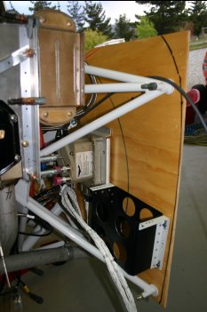 |
| This is some possible thoughts for the RHS, I want to get the ECUs and Batteries as low as possible on the firewall but also balanced between the left and right sides. More emails with the USA guys - hopefully we can come up with a good solution with them and others in the future won't have to go through all the same pain yet again. | 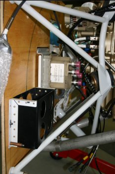 |
Fri 30 September 2005 | |
| Mahlon and the AeroSance people seem to be on the case and are working through the FADEC issues - more updates to come. In the mean time I'll focus on other things. | |
Tue 08 November 2005 | |
| Also received today was the FADEC 'fix' from Aerosance. I'm still rather disappointed with the lack of communication / the current "solution", more discussions needed. | 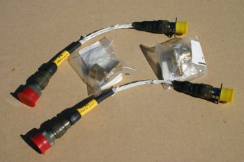 |
Thu 17 November 2005 | |
| I went back with a fresh mind to the FADEC harness. The next step is to break up the bundling that AeroSance had provided. Careful un-wrapping and snipping to free the 'short' cables. | 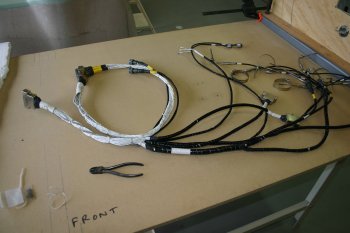 |
| After some time I think we are getting to a better set of options. It may be a combination of simple elbows and extensions for some parts and re-bundling - I'm hopeful. It still annoying that no guidance on the 'standard' layout and the path that the cables 'should' take. It still doesn't fit, but I'm a little more confident that it can be re-organised. I also decided to make more detailed notes - hopefully someone in the future won't have to go through the same pain. | 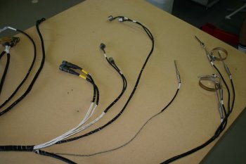 |
Fri 18 November 2005 | |
| Continuing with the FADEC harness I removed most of the tie wrap back to the 'big knot'. Then with the wooden firewall we started laying the harness back out. | 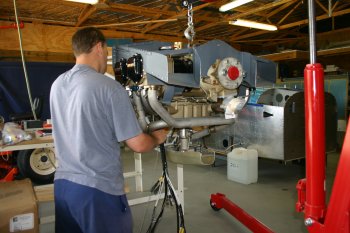 |
| After more thought I think a RHS middling point for one of the ECUs with the other on the lower LHS might work. The temp probes look like they should be OK - once I undid all the bundling it didn't tie the throttle temp too close to the EGT / CHT leads. Several revisions / repositions / re-threads - looking closer to a solution. | 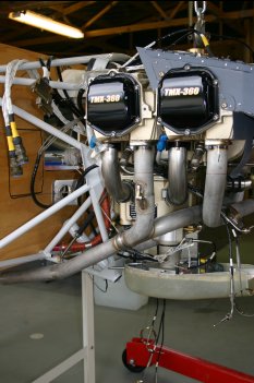 |
Sun 09 July 2006 | |
| Late start, more thought on electrical layout and options. Then started looking at the cabin side FADEC harness. | 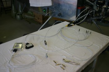 |
| Got everything wired up to a 12V supply with switches etc. but the supply wouldn't hold. The Serial Bus Controller (SBC) which provide the GRT EIS system with engine data wasn't working and the PC software couldn't see anything. | 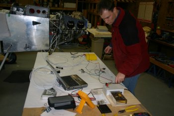 |
| After some more investigation and testing I found the SBC B power / ground were incorrectly labeled by AeroSance - not a good thing! I re-validated all the power lines for the SBC harness and got a data stream coming out ok. The next problem seems to be the ECUs are requesting the fuel pump to come as there is low pressure (ie. no fuel) - the next step seems to be they reboot.... Questions sent to AeroSance. | 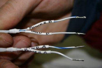 |
Tue 11 July 2006 | |
| Looking at the FADEC low voltage harness we will need a ground point close to the main ciircuit breakers - not a big deal, just another part of the equation. Also looked at bundle routes that might work for the various major cables. | 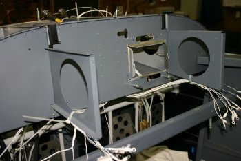 |
Mon 17 July 2006 | |
| I returned to the FADEC harness, rechecked all the plugs / sockets, actually tightened all the connectors. Also temporarily wired the supply lines to the breakers. This time everything powered up OK. Still haven't got the GRT EIS going yet (RS422 -> RS232 conversion needed) but one more step forward. |  |
Tue 18 July 2006 | |
| Cold outside - more electrical planning. I think I might have a RS422 / RS232 solution, but calling in some knowledge from mates in the UK.... | |
Mon 18 September 2006 | |
| Back to FADEC low voltage harness, the current plan for the routing for the forward section. | 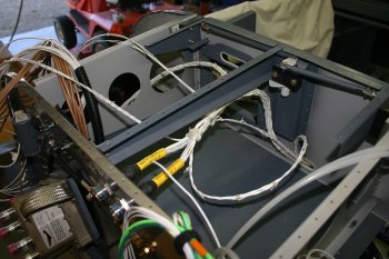 |
| This is the aft section, we are planning on circuit breakers for the power supplies for the various FADEC lines, split left / right for the A & B busses. However the ground points will be elsewhere - it will probably require openning up the power cable bundles, but not something I'm going to rush to do. | 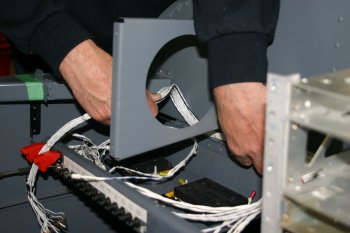 |
Thu 21 September 2006 | |
| Dad continued with the FADEC prep - the main ECU mounting plates need good grounding points for lightening protection. A mini-guided sanding widget was made. | 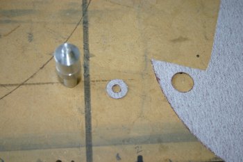 |
| Chucked up and spin, | 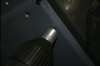 |
| cleaned AL spot. | 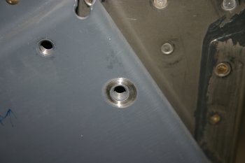 |
| Final mounting of the ECUs with ground straps. | 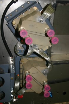 |
Sat 23 September 2006 | |
| So this is the current firewall for a dual battery, FADEC system with dual throttle and pitch controls - we hope.... | 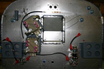 |
| The main cabin FADEC harness needed to be modified to allow connection of the power and ground wires to the breakers and firewall ground respectively. This is a slow careful process of stripping back the sheath and screen braid from each of the 10 power lines. So far for the project not a single pre-made harness has been completely right - I really think 'next time' I would consider making them all from scratch. | 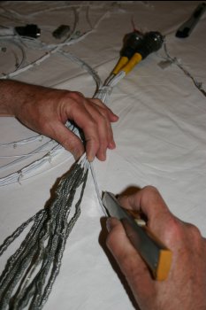 |
Fri 13 October 2006 | |
| With the FADEC system the fuel pump is controlled by a relay - the control is then Auto, Off, On with a traditional 2-1 toggle switch - I'm going to change things slightly and use a 2-10 switch which means I can have Off, Auto, On which makes a bit more sense to me. The relay itself is a bit strange in that it doesn't have 'proper' terminals so I soldered pigtails on and used a 6 way molex connector. I notice some of the other FADEC guys have done similar - good solution. | 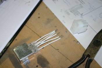 |
Tue 17 October 2006 | |
| Then back to the FADEC power harness. We have decided to shorten the bulkhead / HSA connection. | 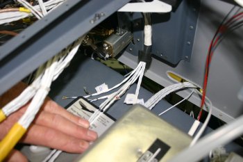 |
| This isn't as dramtic as it may sound, only 3 cables need to be shortened - FAULT_A/B/C/D and the WOT line. The power and LED control lines were extracted from the bundle to help with the cable layout. The high density DB24 connector has a inner shell, but does unclip if you are careful. | 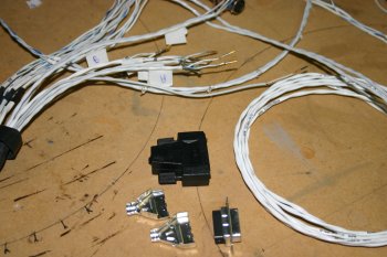 |
Wed 18 October 2006 | |
| Dad put the finishing touches to the FADEC harness modification and re-did the labeling and sleeving. | 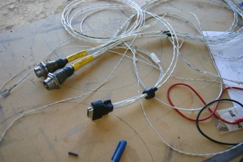 |
Thu 19 October 2006 | |
| Only a few hours on the project today - I re-worked some of the SBC harness should enable things to lay a little better. | 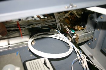 |
Sat 21 October 2006 | |
| One of the last items on the main FADEC harness is the ECU to SBC link. By default it comes with about 2m of cable and a 6 way bulkhead / plug connector - I checked that it wasn't critical to retain and chopped it. Then a small bit of soldering and cirmped pins for the RS485 A / B lines. | 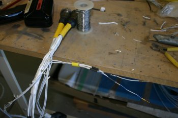 |
Sun 22 October 2006 | |
| After a trial fitting of the FADEC / SBC connection, I decided to remove the pins, shorten the connection further and solder it permenantly together. | 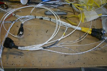 |
Tue 16 January 2007 | |
| We removed the engine to provide better access. This is the current firewall layout for a dual battery / fadec configuration. | 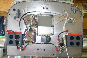 |
Wed 17 January 2007 | |
 | |
 | |
 | |
Sat 20 January 2007 | |
 | |
Sat 03 February 2007 | |
 | |
 | |
Sun 11 March 2007 | |
 | |
Mon 12 March 2007 | |
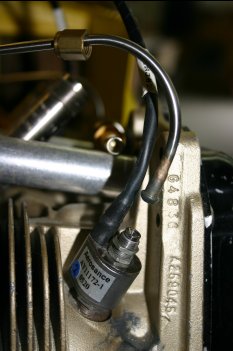 | |
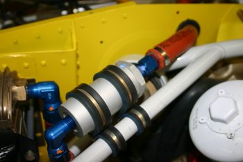 | |
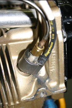 | |
Fri 27 April 2007 | |
| Not feeling well, but got a couple of bits sorted - the MFD2 and PC RS232 feed from the SBC needed some form of termincation, I decided an old fashioned Din5 socket was a suitable solution and unlikely to get confused with anything else. | 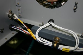 |
Tue 01 May 2007 | |
| As a small diversion for a couple of hours we did some calibration testing on the FADEC sensors - the CHT / EGT probes provide the engine with key data and that is then passed onto the GRT EIS / avionics. Using a meat thermometer and a ball of warm / boiling water we tested the probes. I wasn't too worried about absolute accuracy but having everything in sync is more important. We found the CHT were +- 3 degrees F and the EGT seem to be within 5 or so, although hard to test as they are more sensitive with less damping than the CHTs. | 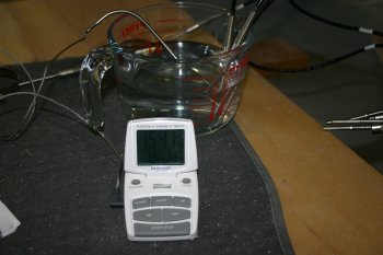 |
Wed 02 May 2007 | |
| I spent a couple of hours working on the FADEC harness, it is a mixture of undoing / splitting the factory wiring and trying to manipulate the cables back into simple / tidy layout - not simple! | 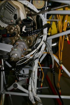 |
Thu 03 May 2007 | |
| I continued with the unwrapping / re-wraping - sorted the LHS / cylinders 2 & 4 probes, not sure of the best path behind the engine yet. | 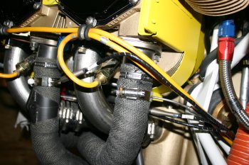 |
| Also re-wrapped the J5 / 6 connectors and SSA lines. Doesn't look much but time consuming. | 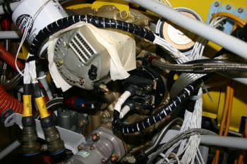 |
Sun 06 May 2007 | |
| Spent more time compressing / sorting the FADEC harness to try and make it 'neat'. |  |
Mon 07 May 2007 | |
| I was back to Adel clamp pain and trying to fix the cabling so that it doesn't rub / bind on anything. | 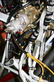 |
| Also safety wired the FADEC ECUs and added some support for the P2 throttle push/pull cable. | 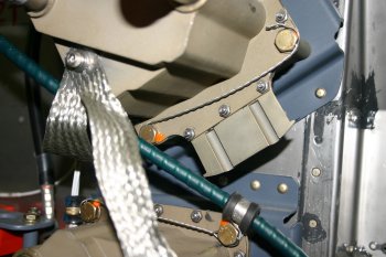 |
Sat 12 May 2007 | |
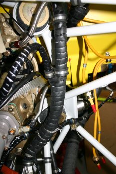 | |
Tue 22 May 2007 | |
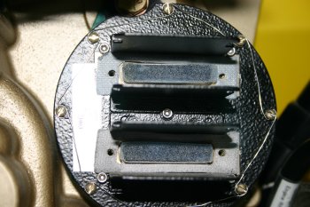 | |
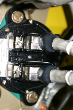 | |
Wed 23 May 2007 | |
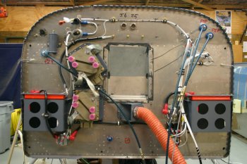 | |
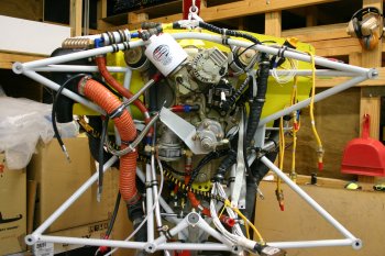 | |
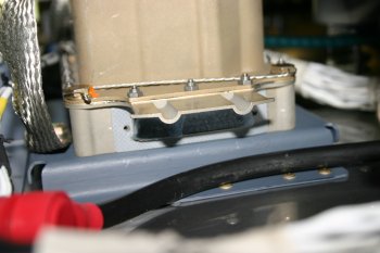 | |
Thu 24 May 2007 | |
| I did the safety wiring and cable tie on both the ECUs - looks simple, but not easy to get to at the back of the firewall with the engine installed. | 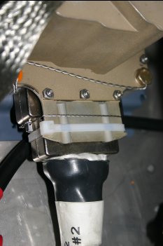 |
Tue 19 June 2007 | |
| This was probably the most challenging of the PCB designs - the FADEC SBC RS422 to EIS RS232 protocol conversion. Although it ended up being a fairly simple board in the end, the research and lack of experience with this type of design / components was difficult. The comercial options are about US$80 and have problems with power supply (they use the RS232 DTS/RTS lines for power - which we don't have). However it worked first time and seems to work well - the success was really quite sweet. | 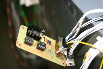 |
Fri 20 July 2007 | |
| The newly announced AeroSance FADEC EDU (Engine Data Unit) arrived. This is a new option provided with the SBC that provides a logging platform for the FADEC system. It should store upto 1000 hours of history on the compact flash card. |  |
Tue 07 August 2007 | |
| Got the EDU mounting cut and drilled, then more cabling / wiring. | 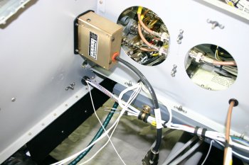 |
| Reterminated the ECU / SBC RS485 connections - provides better routing and pins for future options if needed. | 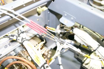 |
| The EDU is a bit of a problem to do up - the #6 washers won't fit and #6 nuts can't get a socket set on them. One of those little details that seem to have been missed in the final design review process. | 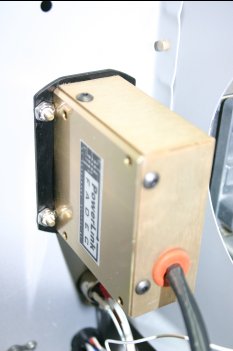 |
Fri 10 August 2007 | |
| Finished the wiring for the EDU. Still need to make a #4 spacer to join the two DB9 together. | 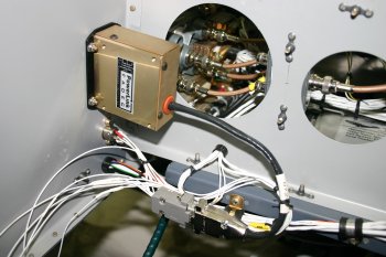 |
| Home | Carl Morgan | Previous|Next|Latest |