Flaps |
|
| I got bored after a couple of hours so then I started looking again at the flap actuation assembly. After more investigation I found several parts that could be worked on. | 
|
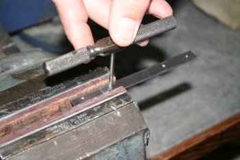
| First simple bit was the flap push rods. Cut and then drill / tap the ends. Takes a while but another thing ticked off the list ready for priming. | 
|
| I also did some of the brackets and motor support components. Hopefully tomorrow will be more productive. | 
|
|
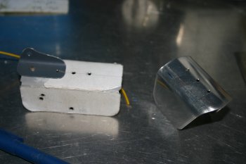
| Meanwhile I continued with the flap assembly. I re-made the angle bracket to hold the flap motor, be careful of which end / side the mounting tab should be (don't ask me how I know....) | 
|
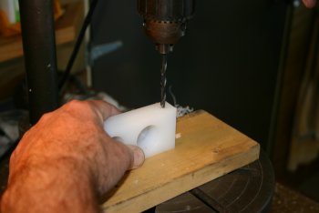
| Drilled the plastic blocks with #10 holes. | 
|
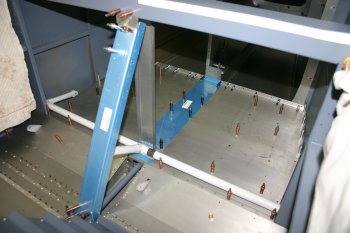
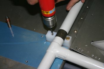
| And then mounted everything up. The lineup looks good and provides the foundation for the flap covers. | 
|
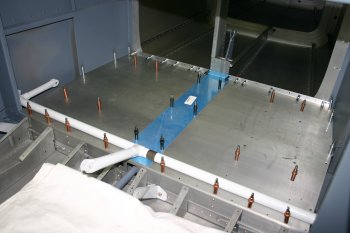
| The top plate for the flap front cover to the cockpit brace has to be fabricated and bent to 181.7 degrees - yeah right. I made a template and cut / filed it out. Then the sheet in the bending brake and got something close to 180 degrees. | 
|
| After pilot drilling to #40's the basic lineup looks a little tight. The flap brace is currently 'too long' so the holes need the be moved towards each other slightly. I'll wait for final drilling for the new fuselage. | 
|
|
| | 
|
| | 
|
|
| | 
|
| | 
|
| | 
|
| | 
|
| | 
|
| | 
|
| | 
|
| | 
|
| | 
|
|
| | 
|
| | 
|
|
| Next up were the flaps. Got them both down from storage and sorted some new piano hinge pins. | 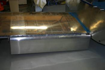
|
| Then mounted the RHS aileron for alignment of the flap. | 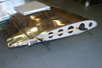
|
| The short version is: both flaps were binding on the inboard edge against the fuselage. | 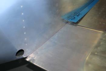
|
| and were not in trail / lined up with the aileron. | 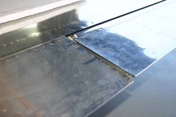
|
| After (more than expected) filing and shaping the inboard upper skin of the flap, it could travel to the fully up position and also looks really good in trail with the aileron. It may need some more trimming for heat expansion / paint etc but I'll wait and see once I've got the flap system fully rigged. | 
|
| Obviously I had to do the LHS flap also, second one, as per usual was significantly fast as I had a good idea of what I was aiming for. | 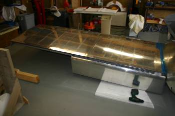
|
| Then I started looking at the flap push rod cut out. This isn't a simple hole, but more of a shaped gap..... I started with a UniBit from the under side of the fuse. | 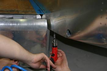
|
| Final step for today getting a push rod to about the right length and sorting a power source for the flap motor. Early finish today, out socialising this evening. | 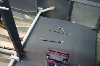
|
|
| My job for the day was sorting the flap push rods. The first step is to drill out the rivet location on the underside. | 
|
| The first guess was based on information from Dan C site. In the end the side shape was pretty close but the lower shape was out and had to be worked on imperially. | 
|
| Then it was scary tool number 2 - Rotary burr. Normal principle, lots of little changes, then testing and then a little more change. | 
|
| The shape took quite a long time to refine. One problem was until I got close to the final shape I couldn't mount the push rod and get full up or full down flap position. | 
|
| This is the final shape I ended up with. It may still need extending forward / inbound slightly but this is the minimum. | 
|
| | 
|
| Once I got the access hole the right type of shape. The next step was trying to sort the range of travel. | 
|
| I tried adjusting the screw thread both ways, but ended up with almost the minimum length possible. | 
|
| The next step was to take the shape and duplicate it to the LHS | 
|
| This took a small fraction of the time as I had an template to work from. By then end of the day both flaps were rigged and could be driven to both extremes. Using the flap motor end stops with travel was from 10 to 55 degrees. 45 degrees is 5 more than standard VANs specs so I guess I'll need a stop of some type, not sure how yet..... | 
|
|
| A small item on the todo list was the flap position sensor - I fabricated a tri-anglular bracket, but without a smaller knuckle for the push rod, I can't continue - not sure where to find a different option. | 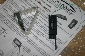
|
|
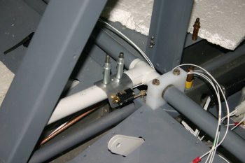
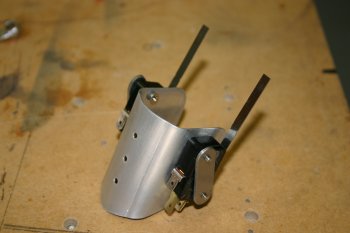
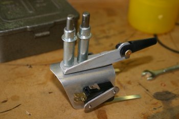
| After various options and research - this is the current principle (which I copied from others). The 'saddle' provids the mounting for both micro-switches, one will be a limit switch (on the up end) and the other will be a ~10 degree switch for the AOA and trim speed control. | 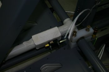
|
| The second generation of proto-type, at this point only #41 drilled locations, I'll wait until the wings are mounted and I can confirm the layout before making the final version. At least the AN3 bolt / nutplate locations are drilled and sorted. | 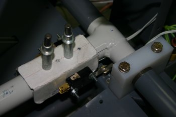
|
|
| Flap switch cabling can be sorted - even if the bracket is yet to be re-done. | 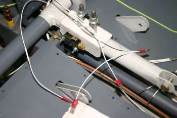
|
|
| Ran the remaining flap power / ground / control lines and got everything working. | 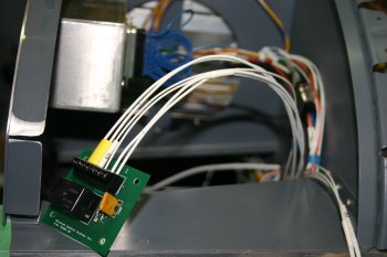
|
|
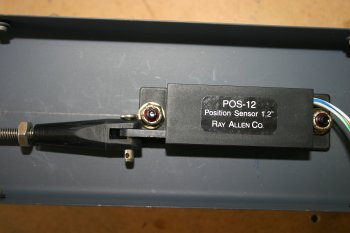
| Then onto the flap switches and sensors. The switches need a little tweaking but look about right. | 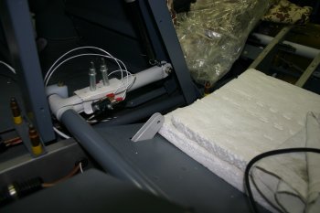
|
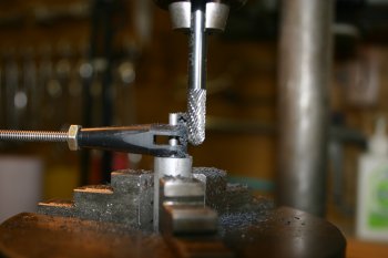
| Lots of trial and error testing for the RAC pot and the flap actuator. It ends up being quite long (8" plus) and needing to be mounted very close to the pivot point. The final bracket I'll wait until the wings are back on to allow alignment of everything together. | 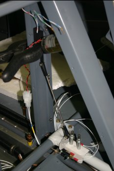
|
|
| Short day - remounting the flaps and also increased the trimming of the upper inboard edges. | 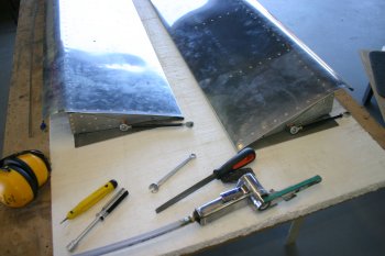
|
| Also back to a problem that we knew about with the flap travel. With the stock standard length pushrods, the flaps go too far down (about 47+ degrees) which results in the skin 'popping out' of the wing trailing edge. Obviously this would not work hence the up microswitch system, but I would like to resolve with the geometery if possible. | 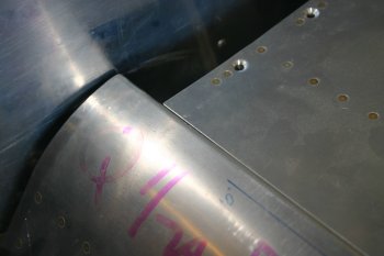
|
|
| The other observation was the bottom flap skin - not sure, but looks like a joggle will be needed in some way. | 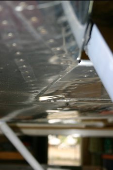
|
|
| | 
|
|
| | 
|
|
| | 
|
| | 
|
|
| | 
|
| | 
|
|
| | 
|
| | 
|
|
| Dad assembled the flap servo mount and installed it. | 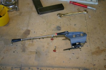
|
|
| Misc bits completed, including tidying the aft section of the fuselage, flap mounts torqued up and everything vacuumed out. | 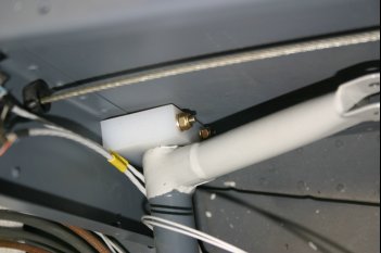
|
|
| A couple of flap pin retainers milled - not much but another item of the list of things to do. | 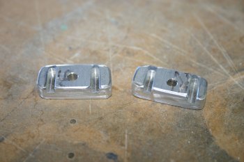
|


