


 |
 |
 |
| Home | Research | Delivery | Empennage | Wings | Fuselage | Finish | Engine | Electrical | GRTDecode | Previous|Next|Latest |
| Electrical | Avionics | Panel | Wiring | Decals | PCBs | ANR Upgrade | |
Panel | |
Tue 31 January 2006 | |
| The rest of the afternoon was spent looking at / working out panel layout. This is something that has been mulled over for a couple of years, but with the Stein ordered becoming imminent some decisions on layout need to be made. A number of options on side by side vs over under for the GRT screens were considered, and I'm settling slowly on this layout. The principle being the primary MFD plus the electric A/H and OBS CDI being in one vertical group and the backup Airspeed and Altimeter being in the second stack. The radio / nav components are further to the right, although I may bring them more central if possible. | 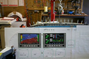 |
| All this is obviously up for modification when we get the actual hardware ;-) |  |
Mon 10 April 2006 | |
| I started looking at the Garmin avionics stack mounting and supports. After some reading and CAD work I set the mill drill up and attacked a bit of AL angle. |  |
| Also did a plate for the rear side. |  |
| The first cut - looks promising, the alignment of the front facias is pretty good, but could be tweaked, and I used #8 tapped locations rather than the correct #6 screws so that will need re-working anyway. |  |
Tue 11 April 2006 | |
| Round two - the front two AL angle supports, this time drilled and tapped to #6 screws. |  |
| The avionics rack - looking good. |  |
| Also put all the harness mounts onto the trays to make sure things didn't 'move' - they did but looks right now. The Stark harness looks fine, although some of the lengths that I requested don't seem to have made it through the process, so some re-work will be needed. |  |
Tue 18 April 2006 | |
| I spent the first part of the day infront of the CAD screen trying to get a working layout for the panel. Then with some locally sourced AL sheet I started making it into a mock panel. We are currently debating whether to stick with the two part panel that we already have (cross bar at the bottom plus normal panel) or to replace the whole thing with a single panel. |  |
Wed 19 April 2006 | |
| I continued with the panel layout stuff. After more thought I decided to make a 'half panel' and the new option is for the master / ECU control to be on the LHS of the GRT MFD - tight but could work OK. |  |
| Then it was more prep work for a wood bed on the milling drill to mount the panel. The working area is about 8" deep by 18" wide, so the panel will need to be done in 4 or more sessions. |  |
| Completed the test drilling for the corners and switches - getting late, so will wait until tomorrow for the milling work. |  |
Thu 20 April 2006 | |
| Continuing with the panel milling - we used a 3mm bit. Boelube was used as a lubricant, that worked for the first one and half sides - then the bit broke! Too small (and possibly not enough lube). |  |
| We switched to a 1/4" mill and continued, the center section was cleco'd down and we used straight turps as a lube - worked better. |  |
| The result - a reasonably clean edge but still needed a bit of file work to get rid of the sharp burrs. |  |
| The mock up in the aircraft. The next questions are based around the canopy frame and where is comes down to, this is about as low as the MFD can go, although the switches can move a little. More prep work to complete first and maybe the new .040" forward skin before re-mounting the canopy. |  |
| Flipping the mockup panel to the RHS, I laid out the Garmin stack location. Same deal, 1/4" drill and then milling the rectangle. A few little problems with the exact mill size (slightly less than 1/4") but looing promising. There will be a small gap around the stack if I use the recommended 6.3" width - I guess that is why we are doing the mock up..... |  |
Fri 21 April 2006 | |
| I continued with the avionics rack, drilling and tapping 3 locations each side. |  |
| Then the mock panel was drilling / recut for the avionics rack - some refinement needed for the upper cut. Also played with using a smaller cut out for the EIS4000 and flush mounting it from behind - I think it might work well. |  |
Tue 02 May 2006 | |
| The other good news is the proposed MFD / switch layout seems to work OK. | 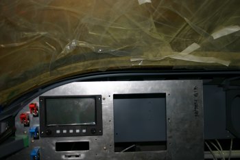 |
| It is getting rather tight in that corner but hopefully the circuit breakers can go on the lower bar and the rest of the switches in the centre section. Note: the EIS and avionics stack won't be on this side - just testing cutting process. | 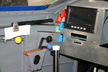 |
Wed 03 May 2006 | |
| I spent the first part of the day doing more research and CAD layout and in the afternoon I re-tried the avionics cut out, mixed success. Sorry no photos - forgot, but you've seen it before.... | |
Thu 04 May 2006 | |
| Half day with other things this morning, I continued with learning process, I've now sorted the upper and lower edges for the avionics rack. | 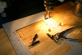 |
| Also tested the AOA display, not sure yet where we are going to locate it as panel space for vertical components is very tight. | 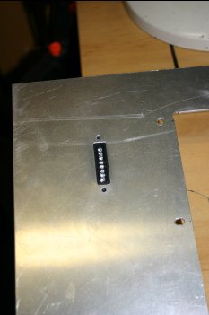 |
Fri 05 May 2006 | |
| Got to the point where I have to make some real decisions for the panel. I've proven the process for the various parts that I want to fit - now it is layout. Spent a few more hours refining the layout in CAD, then printed it all out and got the dimensions sorted. | 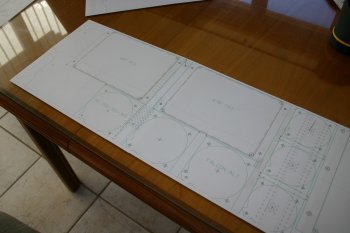 |
| Then mounted the panel up on the wood surface, including registration pegs so I can re-locate as needed. The main panel will be done in 'two' halves and then the outboard bits, center middle, and upper edges will need to be done seperately. | 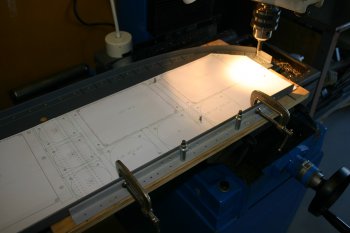 |
| I started by going around the LHS mounting locations, most are #6 screws. Something that took quite a bit of time was working out the 'fudge factor' for the table lead screws. They are pretty accurate but have up to about a 5% error, which in a 80cm side-to-side is nearly 8mm. Lots of calculations and then checking and re-checking. | 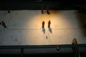 |
Sat 06 May 2006 | |
| I continued with the panel, marking and drilling the RHS screw locations. | 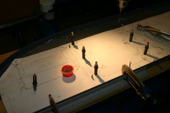 |
| Then I moved onto the round instruments on the LHS side. | 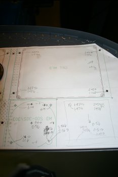 |
Sun 07 May 2006 | |
| Before continuing with the final panel round instrument, I re-tested cutouts and the locations of the off-set locations. | 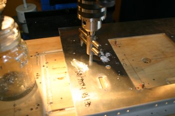 |
| On the last test fly-cutter hole, the work jammed and the drill shaft broke! I started re-making a new one on the lathe. | 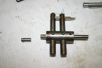 |
| In the mean time I continued with the off-set / corner locations on the final panel. The sequence of instruments is now fairly locked in - A/H, OBS-CDI, ASI, ALT. | 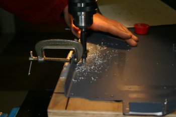 |
Mon 08 May 2006 | |
| First up I continued with the new fly-cutter fabrication. | 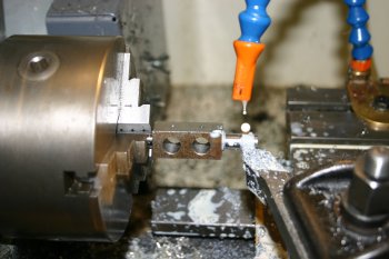 |
| Finally - no more procastenation. I drilled the corner locations for the MFDs, | 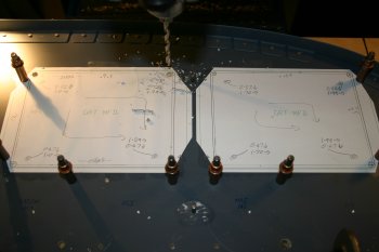 |
| and then used the milling bit to shape the rectangular holes. With the previous experience I cut about 2mm inside the final shape on the first cut, then went back with lots of lubricatent for the final cut. | 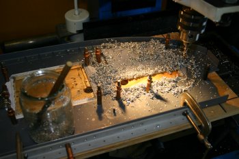 |
| After a sucessful MFD cuts I moved to the EIS4000 cutout, rather than a large hole and normal attachments, I'm going to try the rear mounted option. | 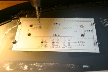 |
Tue 09 May 2006 | |
| Continued with the EIS cutout, the lower locations for the 3 buttons didn't come out that well - they will need cleaning up in some way. | 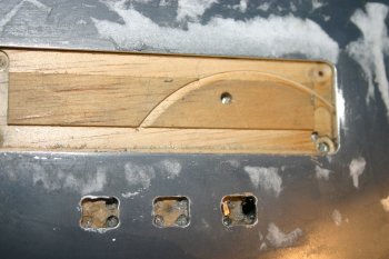 |
| Then I started the biggest of the panel cuts - the avionics stack. I took it really slowly and was taking .1mm of material off at a time on some of the final cuts. Nearly there - the audio panel needs to be slightly wider and slightly taller - but it is within .5mm..... | 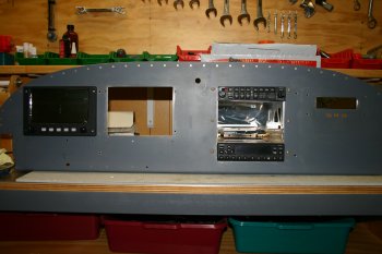 |
Fri 12 May 2006 | |
| More testing with the dummy panel - I think the guarded switches looked a bit to much, but I would still like to get the engine ECU controls in this area. One piece of good news is the round instrument / MFD gap looks like it should work well. | 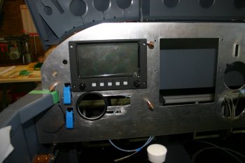 |
| To finish the day I sorted the audio panel cut outs, multiple small passes. | 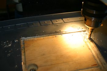 |
Sat 13 May 2006 | |
| Then onto the round instrument holes, after another test with the fly-cutter, I used a backer which worked well and meant I good cut from the front surface. | 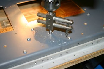 |
| There is a lot of holes and not much AL in places.... | 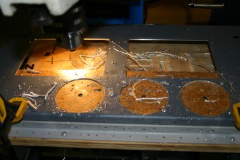 |
| I mounted it up in the cockpit, and put the MFD's in - the canopy still goes down OK..... I didn't recieve any mounting hardware for the instruments, FibreLights or MFDs so another order will have to go to spruce before it can be all laid out. | 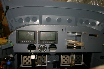 |
| The avionics stack requires a cut out in the forward panel supports for the 430 and SL30. This is the SL30 tray. One problem could be the 430 tray doesn't slide in from the front (the gap is too accurate). | 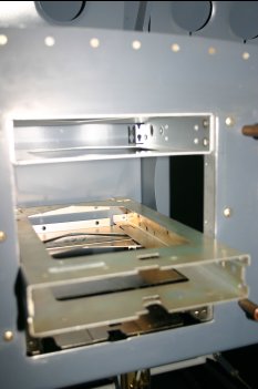 |
Fri 19 May 2006 | |
| Then back to panel layout / ideas. I'm moving away from the master and ECU switches being crammed into the upper left corner and tried moving the masters & cross feed switch to the cross bar location. Also tried the circuit breaker and switch spacing, one leason learnt is the switch spacing (18mm) that I was planning on using is probably slightly (1mm) too small for the DPDT switches - back to the panel layout! |  |
| This is the new plan for the ECU switches - the only problem is the vertical space available for the Angle of Attack LEDs. The AoA could go horizontally, but somehow makes more 'sense' veritcally, I want it in the primary visual scan and don't have a solution yet! |  |
| Difficult to see from the photo - the right hand side of the bar seem to be OK layout wise with most of the B buss circuit breakers. The center section will have the switches and possibly the push/pull controls. |  |
Mon 22 May 2006 | |
| No photos today - most of the day spent 'fighting' with the panel layout, CAD and sitting and staring at the problem. It is a frustrating time at the moment - very slow progress and lots of thinking / dependancies on decisions. The panel and cockpit is so visibile that I want it right but we only get one go at drilling / cutting it. So far I'm happy with the current result but not having all the parts and not knowing quite how I'm going to deal with some of the 'bits' doesn't help. | |
Tue 23 May 2006 | |
| Half day, after re-working the measurments again, got the A/H locations sorted. Normal deal and then fly cutter. | 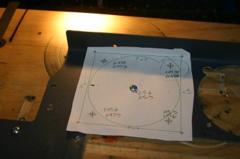 |
| Still struggling with the layout of the upper left corner of the panel and in particular the Angle of Attack indicator and whether I can get the ECU switches along side neatly. This is the best we can come up with for the moment, the good news is it should fit, the bad news is the upper stifferening angle will need significant rebating - I think it is a good idea, but I'll sleep on it. | 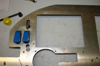 |
Wed 24 May 2006 | |
| Various research and trialing the annunicator ideas that I've got. This is a piece of plexiglass that I've milled a step in. A bit chunky but maybe a valid principle. | 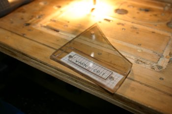 |
Thu 25 May 2006 | |
| After a local trip to scrounge some materials, I found this piece of trim from an aluminium window beading. Then some drilling and milling. The rest of the afternoon was spent trying to find an LED solution - not proving easy! | 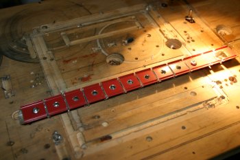 |
Fri 26 May 2006 | |
| Yesterday's material collection included some clear acrylic, a wider block. Milling went really well although it is a little thin. | 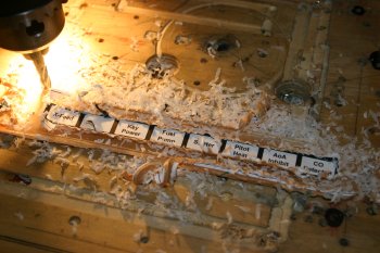 |
| The net result - looks good for night time illumination. | 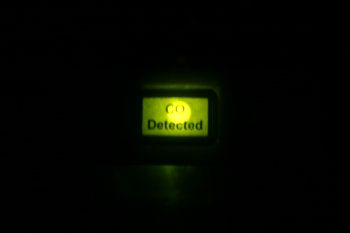 |
| The day time - useless! Back to the 'net for more research / re-think. | 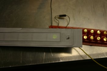 |
Fri 02 June 2006 | |
| I finally gave up putting off the AoA / ECU switch panel drilling. | 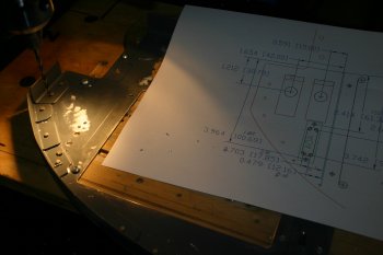 |
| The basic corners and mounting locations were simple enough for the AoA, the problem is the upper angle support. | 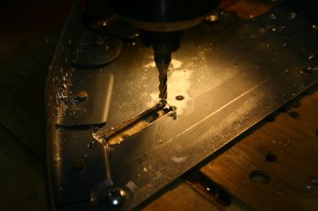 |
| With the new end mill, I carefully rebated the angle for the back fixture of the indicator. | 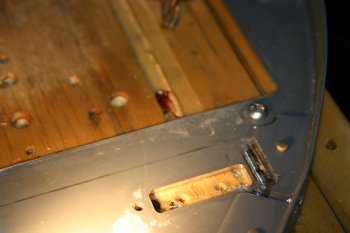 |
| The AoA fits nicely (maybe a little too accurate / tight for paint) and then the ECU switches were checked and drilled. Really pleased with the result, but glad it is done and works. | 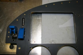 |
Sat 03 June 2006 | |
| Half day, cleaned up the EIS switch cut outs - may need a little more for the upper edge, but much better with the new (smaller) 3mm mill. | 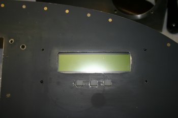 |
Thu 08 June 2006 | |
| Various bits of paperwork today, including getting stock materials for the annunciator panel - think I might have a solution! | |
Fri 09 June 2006 | |
| More design work for the GRT / avionics layout. Also got another lead on parts for LEDs - probably make yesterdays order redundent - Murphy and his mate strikes again! | |
Tue 27 June 2006 | |
| Then moved onto some more cutting on the panel. The TruTrack autopilot head arrived last week with the Stein part 2 delivery. I couldn't find any offical details on the mounting dimensions so just went with measurement and then a test cut. (For reference, 2.52" for the main cutout, #6 on a 2 and 5/8 between centers). | 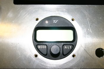 |
| Then onto the real panel. Also increased the clearance on the AoA cutout and EIS buttons. They already 'fitted' but a paint layer would have been too much - extra .4mm gap now. | 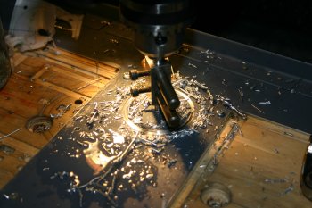 |
Wed 28 June 2006 | |
| We have come to a convenient point in the panel work where most of the major cuts are done for the components that we have in New Zealand. I've decided to 'install' the stuff that is available and use it for some of the wiring, knowing that we will be removing everything, completing more drilling / layout and then painting before final assembly. | 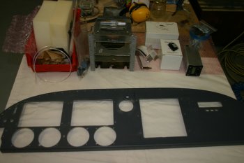 |
| Didn't take as long as expected (about 2 hours) currently using scratch screws / nuts - but everything fits so far. The empty round instrument will be the electric A/H. | 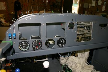 |
Wed 05 July 2006 | |
| Finally took the plung and started the drilling of the cross bar. | 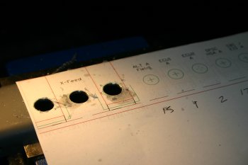 |
| The LHS went well, but I messed up slight on the RHS. Not a biggy and 'others' probably won't notice but it is at slightly the wrong height - just enough to REALLY annoy me. | 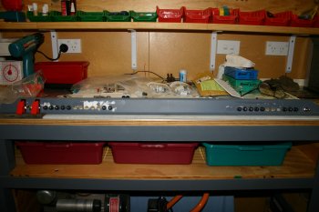 |
Thu 06 July 2006 | |
| Continuing with the Circuit Breakers - I made a couple of bus bars - not sure yet if I'm going to put it on the upper or the lower locations. | 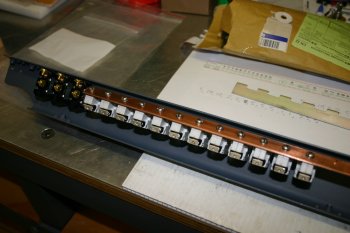 |
Thu 13 July 2006 | |
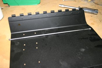
| Meanwhile I went back to the panel and in particular trying to work out a method for protecting the bottom of the breaks and hopefully providing some mounting real-estate for the fuse blocks. This was the first option but didn't provide a wide enough base for the fuses. | 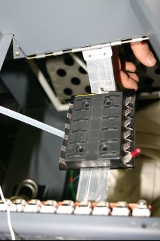 |
| With the basic profile sorted, I started on a full size .032 panel - takes time to get all the alignment right - the forward hinge is permanent, the rear hinge pin will be removable. | 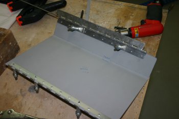 |
| First looks with cleco clamps looks encouraging... | 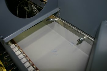 |
Fri 14 July 2006 | |
| Continuing with the RHS panel tray - I finished drilling the forward hinge. | 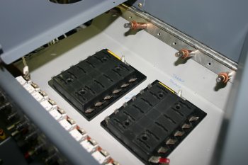 |
| Then onto the LHS tray. | 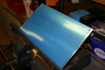 |
Sat 15 July 2006 | |
| The P1 side is slightly wider (the master switches) but same principles - second instance, as per usual, was quicker. | 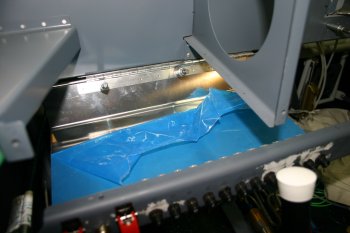 |
| If you are going to do anything similar - don't rivet the lower location on the sub-panel. A spacer was used on both sides to adjust for the step between centre and outboard sections. | 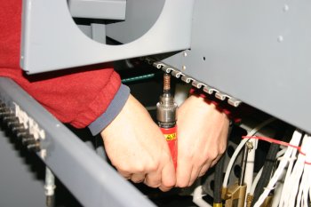 |
| Once the basics were done, more trimming / shaping was needed to clear the fresh air inlet ducts. | 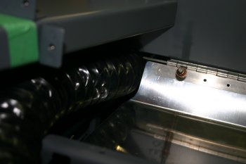 |
Tue 01 August 2006 | |
| Today I was back on planning and documentation, but another area being thought about is the annunciation - this is the current thoughts, a block of 3x2 in the center for the non-critical things, and a set on the far left hand side for the critical FADEC / alternator etc alarms. | 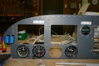 |
Sat 12 August 2006 | |
| We got the Electric RC Allen A/H (mega bucks) a week or so ago, mounted up for the first time today - very tight on the LHS between the instrument body and the panel rib - but I think it will work OK. | 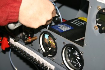 |
Thu 14 September 2006 | |
 | |
 | |
Thu 21 September 2006 | |
 | |
 | |
Sat 23 September 2006 | |
| Dad turned up a guard for the starter switch - we might change this, but in principle this is fine for the moment. | 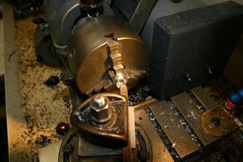 |
| I took the current plan for the switch layout and drilled up the test sheet. Looks promising, but I'll sleep on it. | 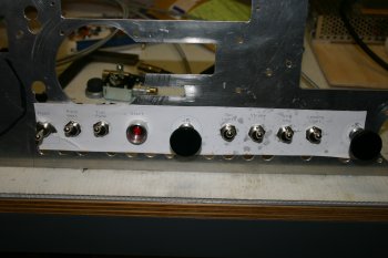 |
Sun 24 September 2006 | |
| I finally finished thinking about the switch layout and did the drilling of the lower cross bar. | 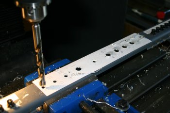 |
| Also knocked up a couple of backing plates to fix the alignment keys for the switches - this keeps the switches moving up / down (and not off to a strange angle) | 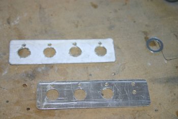 |
| This is the current state - seems to work and keep everything in a logical order whilst maintaining spacing. | 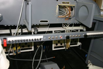 |
Wed 27 September 2006 | |
| One of Dad's purchases yesterday was an XLR socket - this will be wired to the A and B hot busses as a feed inside the cockpit or for charging the batteries without removing the cowl longer term. I removed the original toggle switch location and drilled it out. Of course I didn't have a hole saw the right size.... | 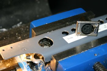 |
| More wiring termination and setup - I think the lower bar is now fully drilled. One interesting note - the XLR socket has pin 1 slight further forward than the other 2 pins, I'm guessing this is for audio grounds - getting the ground before the 'signal'. I've wired pin 1 to ship ground for the 'same' reasons - made sense at the time. Still waiting on the Stein order, then I can finish the tunel wiring and then move onto the panel proper. Tomorrow is gardening duties, back to plane on Friday. | 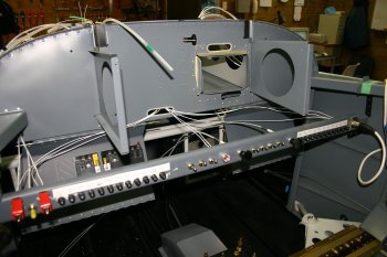 |
Fri 06 October 2006 | |
| Sorted the central bauden cable with an adel clamp on the sub panel. The right cable is going to be more of a problem - the tray gets in the way - thought needed. |  |
Sat 14 October 2006 | |
| The weather suddenly has improved - late 20s but moderate winds. I decided to go for it as it is only 'hidden' parts that needed a quick coat to enable us to continue. Scuffing, AllSol and de-oxidine. | 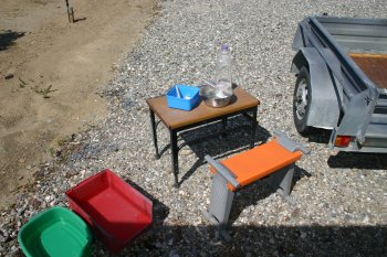 |
| Then prime and black top coat. Wind was marginal but OK. Then back to a little more wiring. | 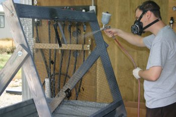 |
Mon 16 October 2006 | |
| A 'current' panel photo - just for the hell of it. Begining to look right - some more thoughts on USB and music jack locations. | 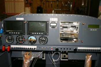 |
Tue 17 October 2006 | |
| With the radio trays fixed, the coax connections can be completed - a few hours. |  |
Fri 20 October 2006 | |
| Whilst access was available I also increased the access hole to the back of the audio panel. | 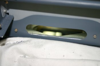 |
Wed 25 October 2006 | |
| Panel re-installed and more cabling. A few checks and then the big power up.... | 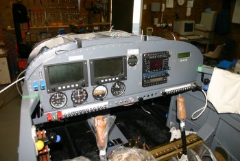 |
| Presto! Working methodically through the various items, everything powered up and no smoke escaped. Some data line / configuration issues to be sorted, but I'll work the documentation first and then go in with a plan. All in all a good way to finish before I have a few days off the project, visiting friends up north - will be nice for a break it has been far too long! | 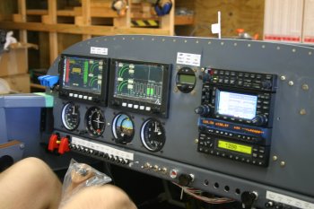 |
Sun 12 November 2006 | |
| Re-visited the AoA push buttons, I would like to get them next to the actual display, but the AL angle along the top of the panel makes if very tight. The dummy template was used again to visualise the layout. | 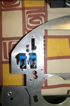 |
Fri 01 December 2006 | |
| To finish the day, I started looking at the annunciator panel front face again - the bits of plexiglass that we have were an option, but not flat enough. I tried heating with a hot air gun, but to get it maluable it bubbled slightly on the surface. Back to square one. | 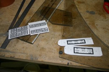 |
Sat 02 December 2006 | |
| The replacement LED board for the AoA system arrived from Rob - thanks. | 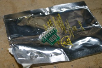 |
Sat 16 December 2006 | |
| Then I went back to proto-typing the annunciator stuff. Yesterday I managed get some smoked 4.5mm thick acrylic sheet and also a test order into RS components for some DIP mountable LED bars. I re-did the CAD layouts and made a new plastic insert. | 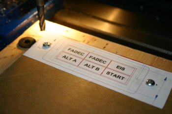 |
| One of the problems is I end up with square corners (rather than filleted / round corners) with the above milling, so more testing for the panel cutout. | 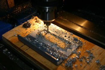 |
| This is the example result, a board with the LEDs will mount behind this. Look like it should work and provide a 'smooth' front surface to the panel. A couple queries are outstanding - one in particular is how well the coloured lights comes through the smoked glass. We will hopefully find out later in the week. | 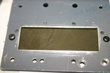 |
Tue 23 January 2007 | |
 | |
Fri 26 January 2007 | |
 | |
Sat 27 January 2007 | |
 | |
 | |
Sun 28 January 2007 | |
 | |
Tue 30 January 2007 | |
 | |
 | |
Wed 31 January 2007 | |
 | |
Thu 01 February 2007 | |
 | |
 | |
 | |
Sun 04 February 2007 | |
 | |
 | |
 | |
Mon 05 February 2007 | |
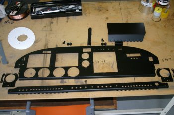
| This was the first time I've really sat down and planned all the labels and markings for the panel. Various CAD drawings, testing, then printing onto acetate and checking the subtle alignment issuses. Generally I'm using Arial font at 3/32" high, takes a while but is looking good now. | 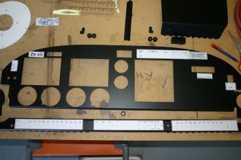 |
| Then with most of the handling / planning sorted, a light rub down and a little more black top coat on the front surface. | 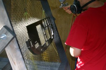 |
Mon 12 February 2007 | |
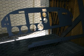
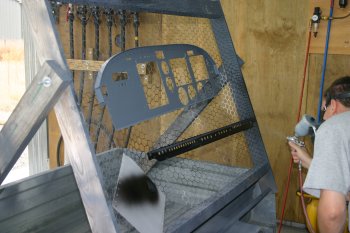
| With the weather looking promising for spraying I started the stripping back to raw AL of the panel. This is so we can use a hardened 2 part top coat. It is a slow process using acetone and sanding. |  |
| This is the first pass at the problem, most of the front surface is done - the rear need further cleaning / prep. |  |
Wed 14 February 2007 | |
| More cleaning / sanding of the panel parts. Ended up using cotton buds with acetone to finish the holes / edges. | 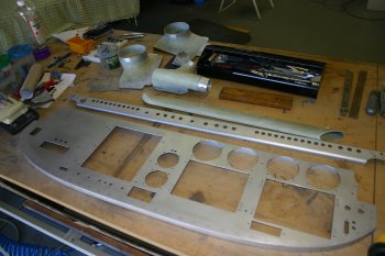 |
| Then more of the old system - firstly a acid wash and then a light self-etch primer coat. | 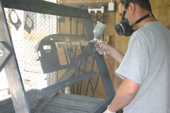 |
| Then the new stuff - this Standox EP filler surfacer - it is designed to provide an epoxy layer with high solids and then be run down. 2 Pack plus thinners. | 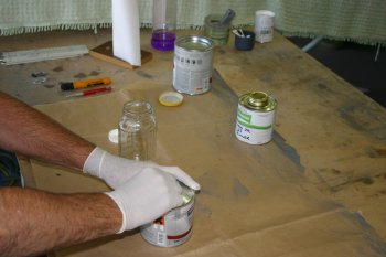 |
| Once everything was coated - into Otago Sun Mark 4 for baking. | 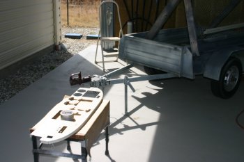 |
| Close up of the finished surface - looks good and solid, still slighty soft at this point. Will need a light rub down to get a smooth base but looks tough and solid. | 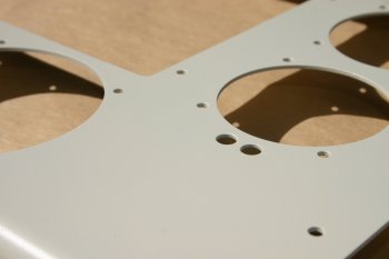 |
Thu 15 February 2007 | |
| Using 1600 wet & dry I cleaned up the top of the panel, just taking the edge off the primer surfacer and prep'd for the new 2 pot top coat. The black top coat went on quite well, but is slightly more glossy than I would like - hopefully it will dry down. Not sure yet if it will need another rub down / top coat for a primo finish. | 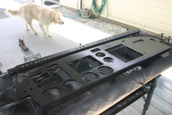 |
Sat 17 February 2007 | |
 | |
Sun 18 February 2007 | |
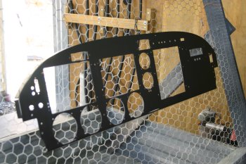 | |
Mon 19 February 2007 | |
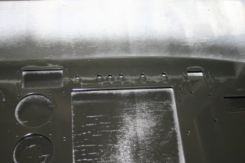 | |
Wed 21 February 2007 | |
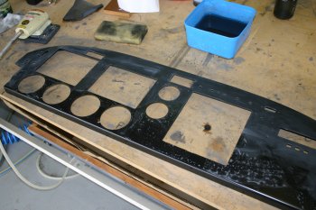 | |
Sat 03 March 2007 | |
| The panel paint had hardened off a bit today and I start looking at the problems. Difficult to see from the photo, but the running out of paint did result in patch dry / sandy areas but probably managable. | 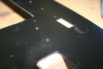 |
| However when I started looking at the cut outs the thickness of the paint is starting to become a problem and a couple of areas chipped badly. The conclusion was rub down (again) and open some of the holes just slightly. | 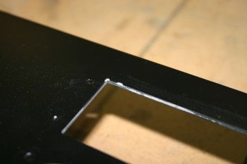 |
| Got the process sorted now (too much practice) but it is coming up really well. | 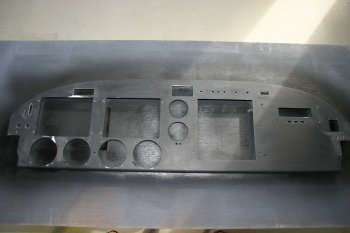 |
| Hopefully the last top coat for the panel - it went on quite well - tomorrow we will see the results. | 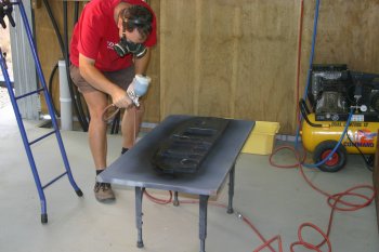 |
| One improvement to the method is to bring the work straight inside and cover with a lid - this reduces the dust. | 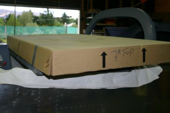 |
Tue 13 March 2007 | |
 | |
Mon 19 March 2007 | |
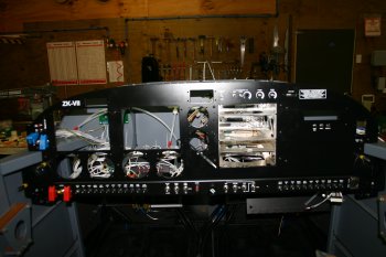 | |
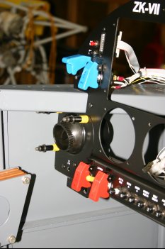 | |
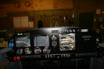 | |
Tue 20 March 2007 | |
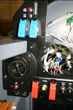 | |
Thu 17 May 2007 | |
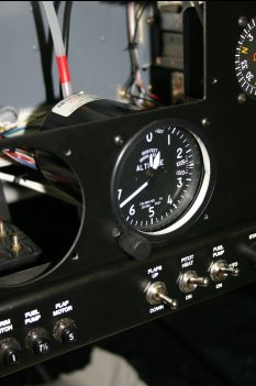 | |
Thu 07 June 2007 | |
| A bits day - more firewall forward tieing / tidying and then onto panel / instrument mounting. | 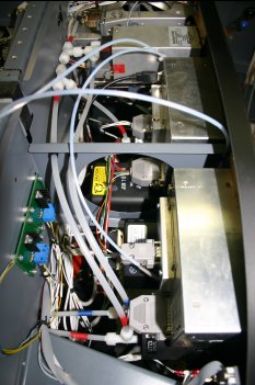 |
| Finished the day with some electrical work and powered everything back up. Also checked some of the new additional bits - CWS, Xfeed sense etc. | 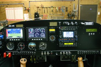 |
Fri 27 July 2007 | |
| Re-installed the RHS drop down panel and started laying in the additional wires for the annunciator displays. |  |
Sat 28 July 2007 | |
| After a load of termination and cable routing - the final annunciator light result. I'm really pleased with it - but it has been a lot of work. I think the visible panel stuff is nearly finished. | 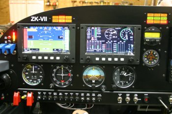 |
Mon 30 July 2007 | |
| More cable routing and allocation. Some of the trim systems needed trimming and terminating too. The main wire harnesses are now pretty fixed and additional core a pain - but simpler now than later.... | 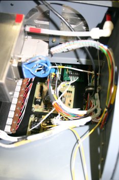 |
Mon 06 August 2007 | |
| I started looking at mounting for the EDU and undoing previous wiring - I hate going backwards! | 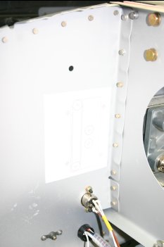 |
Thu 09 August 2007 | |
| I pottered around various stuff - installed the parking brake control cable - the last item to be installed on the panel. | 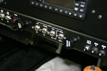 |
| The current panel status - all coming together nicely..... | 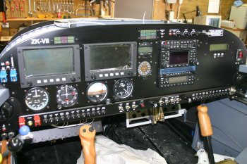 |
Sat 11 August 2007 | |
| I started looking at the fibrelite instrument lighting. The plastic optics need trimming and holding together. I used face cutters to get a clean ish edge to the cuts. I mounted a white LED on the panel support and wired into the NAV light / dimmed panel lights. All seems to work - but difficult to take pictures of. The Fibrelights seem significantly brighter than the traditional bulbs in the compass and CDI/OBS. | 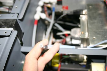 |
Tue 28 August 2007 | |
| Then just a slot for the SD card and some spacers and the logger is mounted. | 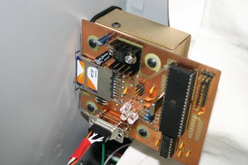 |
| The finished 'look' of the data logger from the front. Still needs some wiring for the second UART input, but otherwise pretty much done. Then I just need to sort the firmware / C code..... | 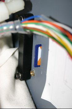 |
| Home | Carl Morgan | Previous|Next|Latest |