


 |
 |
 |
| Home | Research | Delivery | Empennage | Wings | Fuselage | Finish | Engine | Electrical | GRTDecode | Previous|Next|Latest |
| Empennage | Horz Stab | Vertical Stab | Rudder | Elevator | |
Elevator | |
Thu 15 January 2004 | |
| The next major assembly is the elevators. I first laid out all the components I could find for both elevators, although generally they are built one at a time (right then left). | 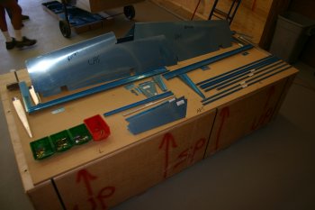 |
| The rest of the day was spent cutting the stiffeners to size, sanding them, deburing various spars and ribs, and generally cleaning up the surfaces of the elevator parts. Pretty tedious but all needs to be done. Made good steady progress, lots more to do tomorrow. So far we have waited to prime all the component parts (hence why I have no completed assemblies) but for the elevator I think we will have to rivet the stiffeners before folding the trailing edge. Not sure in which order we are going to prime things in yet, more thought needed. | 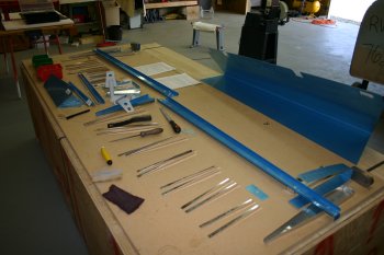 |
Fri 16 January 2004 | |
| Today was more of the same. Lots of deburring and cleaning up of edges. Completed all the elevator components. Laid up the stiffners onto the skins and match drilled. | 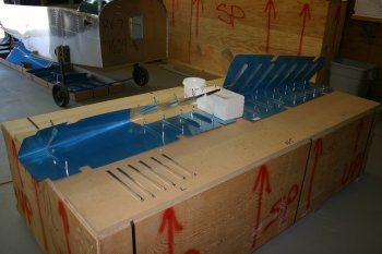 |
| Debured all the match drilled locations and dimpled the stiffners. Doesn't sound like much for the day, but it was a full 11 hours effort. Probably won't go that much further as we will wait for the facilities so that we can prime parts. | 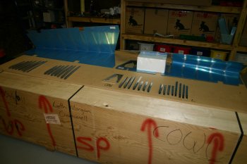 |
Sat 17 January 2004 | |
| We started the day by finishing the elevator stiffener dimpling. We used the pop rivet pulling method for the two trailing edge dimples on both sides of both skins. | 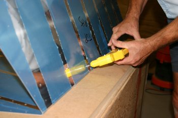 |
| The rest of the dimples were done with the C frame. We then added the elevator skins and parts for the priming pile. Still unsure of the priming order / method so we will move onto something else instead of making a decision :-) | 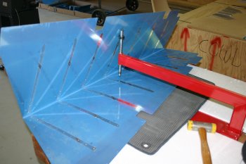 |
Thu 05 February 2004 | |
| Then I moved onto the elevators skins. The stiffener attachment step has to be completed before the surface is 'squashed' which is needed to complete the rest of the match drilling and preparation. The stiffeners now being primed meant progress could be made. I decided to rely on the ALCLAD on the skins for skin protection / anti-corrosion. | 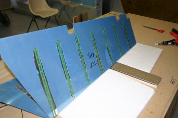 |
| A large proportion of the rivets are easy. The final two aft most rivets (at the apex of the bend) of the second side are very difficult to get to and I thought seriously about using a bucking bar. Before I deviated from the instructions I sent a query to the SoCAL list to see what the guys had to say. | 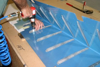 |
| Meanwhile I got on with the other elevator skin. | 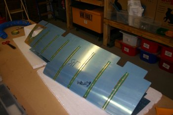 |
| Dad sorted the elevator electric trim stiffener. It needed dimpling and the platenuts fixed. | 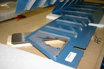 |
| The finished elevator. The theme from the list was just do as you are told. Back rivet them all, the skin will bend that far and it won't cause any permanent damage. I now concur with this opinion and found all it really required was a little more confidence on the man handling of the material. Overall, not a bad day, results are pretty good. Two additional things learnt - The rivet gun uses more lubricating oil than the other tools and 'stalls' if it gets too tight, a little extra oil and high pressure to get it going and everything was fine. Secondly - Don't over drive the rivets on stiffeners, it will result in a slight deformation of the skin (however it isn't too serious) - don't ask me how I know! With the above knowledge, I suggest you set the top skins of the elevators FIRST, then the lower skins. This means any 'dodgy' over driven rivets will be on the lower surface and will not be as visible or bug you quite as much. | 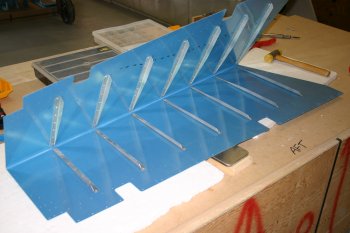 |
Fri 06 February 2004 | |
| Dad spent the afternoon making the flat surfaces for the bender. This is needed for forming the trailing edge of the elevator. The problem in Central Otago, New Zealand is with a 'normal' humidity of about 40-50% no pieces of wood stay close to straight or true for more than about a week. Therefore the first process was to use the 'original scary tool' electric planer to try and make a flattish surface. | 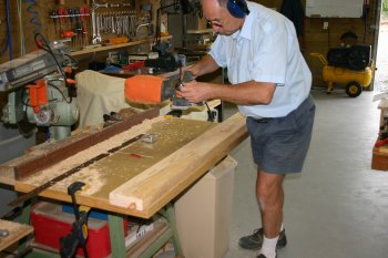 |
| This was then glued to a sheet of plywood...... | 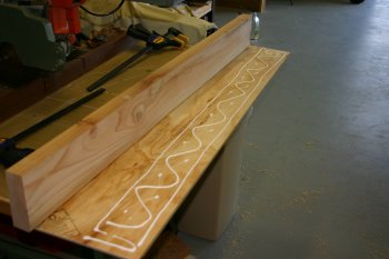 |
| .... and left to set overnight | 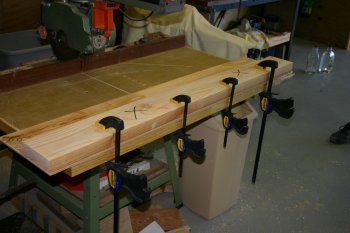 |
Sat 07 February 2004 | |
| Dad continued working on the folding brake. | 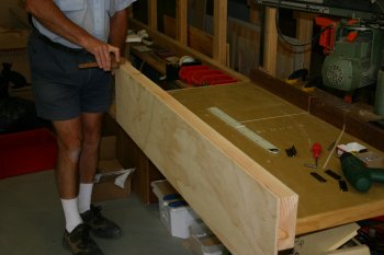 |
| Then it was on to use the new bending weapon. This is something I've been putting off a little. Although the concept is pretty simple, bend the trailing edge of the elevators with nice straight flat skins, and VANs helpfully shows what you don't want as a result the instruction on the actual bender and where you should place the skins are pretty slim (to say the least). One of the reasons for waiting was because we weren't sure on how / if we were going to prime the insides of the skins. The conclusion we came today was that the ALCLAD protection (already on the skins) will probably be fine as long as we look after it and we will just prime the ribs and spars etc. I'm not sure yet about the HS & VS skins we will see. | 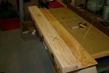 |
| We started cautiously and had the skin about 1" away from the hinges, this was a BAD idea. Progressively we moved the trailing edge closer and closer to the hinge line. | 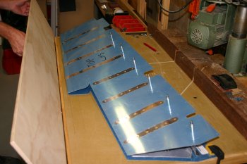 |
| This was the first attempt. Not crisp enough and a brilliant example of the 'don't do this' picture from VANs! | 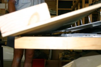 |
| We kept moving closer until we ended up with a standard 1/8" from the hinges (measured by a piece of 1X1X063 angle). This improved things dramatically and we were pretty happy with the results although not quite perfect. I suspect this is something where the 3rd aircraft is really simple (alternatively if you have access to someone that has done it before that probably works too). | 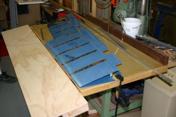 |
| We then moved onto the right elevator. This time we started straight off with the 1/8" angle distance and I was a little more assertive / confident with the pressure. This ended up with a tight flat apex, at first I thought I had overdone it and was not happy. However as we added the ribs and spar it all started to look just great and then the left elevator started to look the poor version. | 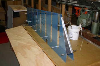 |
| The right elevator outboard end, I think this is what we are meant to end up with! | 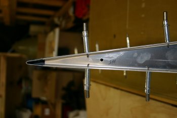 |
| Then the question was do we touch the 'OK' left elevator or leave well alone. I decided that it would bug me too much so I went for it. It all panned out OK and we now have both elevators with nice crisp trailing edges that look good. I'm pleased to have this little challenge out of the way safely, it isn't that hard, just unknown and very limited guidance. Also this bending system is relatively new to the RV7 empennage and a lot of the other builders web sites don't have information on this step. I finished the day starting some of the work on the spar and rib alignment, more tomorrow. | 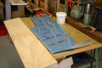 |
Sun 08 February 2004 | |
| Meanwhile I continued with the elevators. The first thing that became obvious was the fluting on the counterbalance ribs needed redoing. This took a fair bit of time but came out OK and most of the holes matched cleanly. | 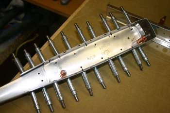 |
| I then cleco'd the whole elevator structure together for match drilling. | 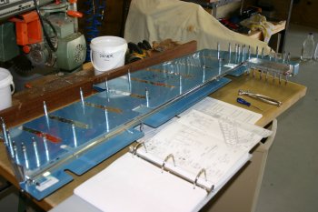 |
| Match drill both elevators. Got about 70% done. | 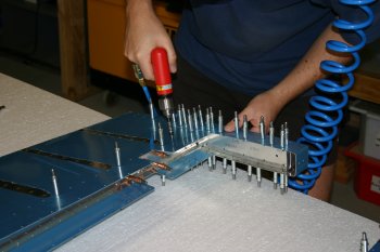 |
Mon 09 February 2004 | |
| I continued throughout the day working on the elevators. Including finishing the match drilling and separating the parts ready for deburring. |  |
| The elevator counter weights are held by two bolts / screw so I drilled the #12 in the lead. This was a slow process but use BoeLube and it all works OK. |  |
| Then it is the normal, take apart, debur and prep all the parts. |  |
| Then dimple all the skin rivet locations, this ended up using most of the dimpling tools available. That was all for today, hopefully another batch of priming first thing tomorrow. |  |
Tue 10 February 2004 | |
| The other part that I would like to get sprayed is the elevator trim tab skin. So I set to work match drilling the Z shaped stock. | 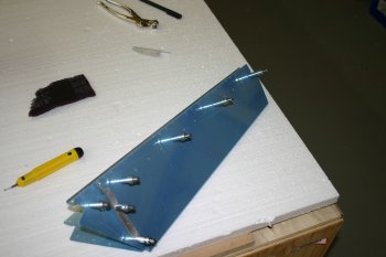 |
| The Z is then countersunk for the skin dimple and piano hinge below. | 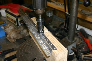 |
| The finished parts of the trim tab - not yet with the 'interesting' tab folds. | 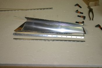 |
| We then spent the rest of the afternoon working through the elevator skins, prep'ing, smoothing, deburring, dimpling..... you get the idea.... Right side is done, left side to be finished tomorrow morning. | 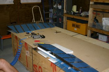 |
Wed 11 February 2004 | |
| Dad finished off the left elevator edging and prep work first thing. | 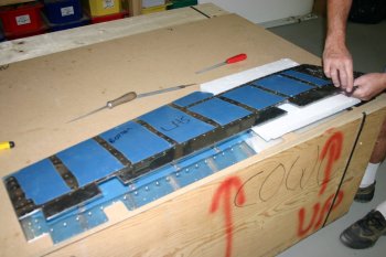 |
Fri 13 February 2004 | |
| Whilst cleaning I realised the aft spar for the elevator trim hadn't been countersunk so I fixed that. | 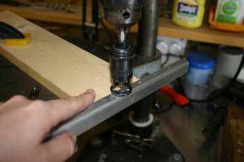 |
Tue 24 February 2004 | |
| Late start today, various housekeeping tasks to tidy up first thing. We decided to see how much of the elevators could be done without the pro-seal for the trailing edge. | 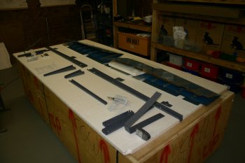 |
| First thing on the list for me was to reduce the lump of lead for the right elevator counter weight. It is still amazing to me that we lighten a few ounces of VS stiffener and then add pounds of lead weight, but I understand the concept. | 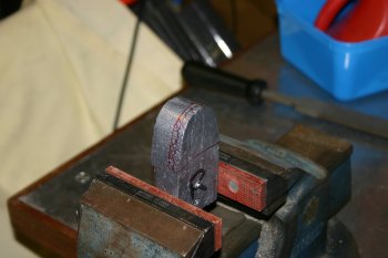 |
| I just used a course pitch handy saw and the vixen file for 'finishing'. Took a little while..... | 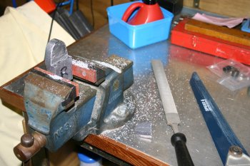 |
| Then it is into the riveting - the end counter balance rib is first. The longeron yoke was struggling to fit over the double flange so I tried shooting them with the vice holding the bucking bar. Worked OK but not as consistent as using the squeezer (probably more my technique / lack of practice than anything else). | 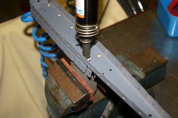 |
| Then the spar reinforcement and nut plates. | 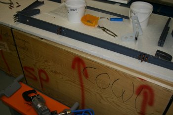 |
| Followed by the flush rivets for the end rib. | 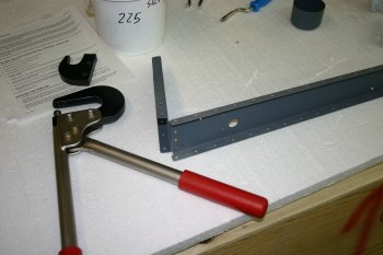 |
| Whilst Dad was using the squeezer / yokes on the right elevator (I was doing the left) I removed the blue plastic from the inner skin surfaces. Next time I would do it BEFORE crimping the trailing edge. | 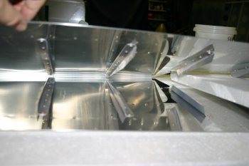 |
| Then the elevator horn. A few tight rivets but all OK. | 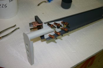 |
| The next stage is to rivet the 4 inner most AD3 skin rivets that join the counter balance skin with the main elevator skin. I just squeezed them carefully. | 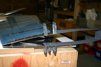 |
| Finally I cleco'd the whole assembly together (left and right). I need to do this to sort the final end rib / spar rivets. | 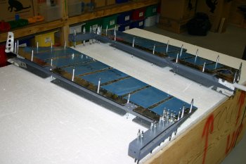 |
| This is the problem, all the other rivets line up and sit nicely but both elevators are out by the same amount. Tomorrow we will have to match drill and workout a plan of action. | 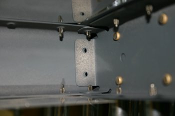 |
Wed 25 February 2004 | |
| First up was the rib / spar drilling. Angle drill needed. | 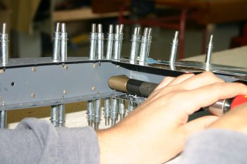 |
| Ended up fine. I suspect the rivets may set a little strangely but that is another day. We are waiting on the Pro-Seal so that the elevators and rudder can be completed (see below for today's developments). | 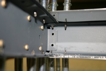 |
| Then we moved onto the bending of the trim tab and elevator tabs. This is an area where I understand most first time builders struggle a little to get a good finish that they are happy with. We are no different and after spending most of today on the trim tab we have learnt a little more but are still fairly confused! The first task is to make a wood 'wedge' to act as support for the bending process. Yesterday I came across a AutoCAD DWG of the trim tab section on one of the Yahoo groups, I butchered this to give me a template for the wedge. The critical piece of information (that isn't stated on the planes) is the inner acute angle of the trailing edge is about 16 degrees. This is needed for the elevator tabs and the corresponding trim tab. The inboard trim tab angle is more complex (more later). I marked up the wedge and cut on the radial arm saw. | 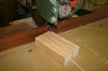 |
| One of the techniques suggested in the instructions is to use a low powered setting on a flush head rivet gun. I'm sure if you are good at controlling the head it might work. I couldn't get repeatable results on the test pieces so I'm not keen unless really necessary. My strong advice - before doing the real thing - have a practice on some scrap. | 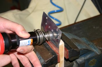 |
| The next step is to crimp the trim tab. The bending brake came back out and was setup. The problem with the trim tab is because it is so small it is very difficult to get an even bend. We were partially successful but I could still see the locations of the hinges if I tried hard enough. Next time, I would probably do smaller amount at a time and move the work along the bending line of the brake. | 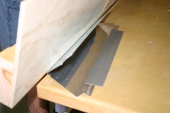 |
| Then it is onto the wedge. We started with the outboard end (smaller) and set it up on the edge of a small bench. | 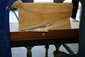 |
| After bending the lower skin with a wooden block and then a flat metal drift to finish it, the conclusion was we were slightly too far into to trim tab material and the wedge shouldn't have been radiused along the bend line. We then flipped the skin over and did the upper skin against a 'cut edge', this worked better although the tip is still not that great. | 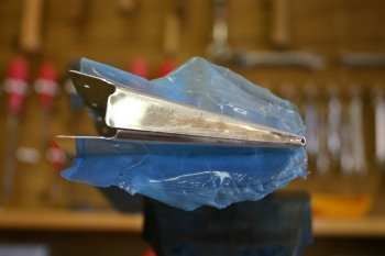 |
| For the inboard end we tried (multiple) different clamping solutions, this was one along the way. Not a good option (not firm enough). |  |
| This was the 'final' solution that seem to work OK. The main face of the tab to be bent was on the upper side with the wedge locked into the skin (upper left dark G clamp / wood) with the matching upper clamped downwards (blue G clamp) and a bracing support locked into the back of the wedge (upper right G clamp) to prevent the skin & wedge moving. This seemed to hold the whole shebang tight and enabled the bending process to be worked on. | 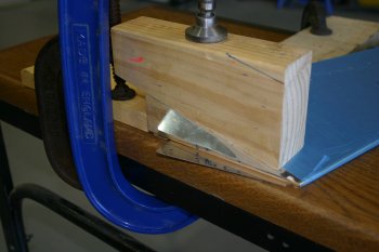 |
| The lower skin bend was OK I aligned the wedge with the outside of the skin forward 'flange' (the bit that attaches the trim hinge) and worked down it with a wooden block and then a large bucking bar (gently). | 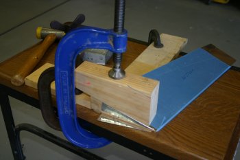 |
| Then it is flip over and re-configure for the top skin. Same bending process again. | 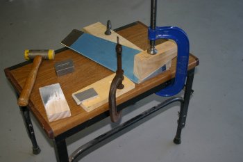 |
| The end result is OK. Not great but probably usable. My problem is that the wedge upper support slipped down during one of the clamping process of the inboard end which ended up deforming the trailing skin shape slightly (difficult to see in the photo - but the bends in the reflection give it away). | 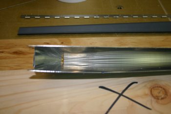 |
| This is the external view of the same problem. Other than that the two end tabs 'meet' but bind and don't sit completely flush and the tip of the outboard end has bowed slightly. That is all the bad news - the good news was I have been warned about the trim tab being difficult so I ordered an extra skin in March last year :-). So today I've been 'practicing' on the spare, tomorrow (or Friday) I'll have to do it for real on the one that is internally primed. | 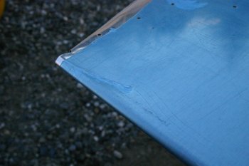 |
Thu 26 February 2004 | |
| I spent about another hour or so cleaning up the edges of the tabs that are to be bent, this is the last time they will be easily accessible. | 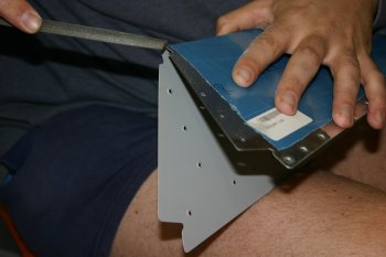 |
| Then it was bending the trailing edge and side tabs of the primed elevator trim tab. The short version for the rest of the day is - Completed five bends and drilled 3 holes. The result is better than yesterday but still not quite as good as I hoped for. The long version with photo overkill follows: I started be crimping the trailing edge of the trim tab. Yesterday we ended up with marks (slightly bowing) around the hinge locations. I therefore started thinking about other options. The best I could think of was using the back riveting plate, the problem was getting the angles right is almost impossible so we didn't use this option in the end and went back to the bending brake. | 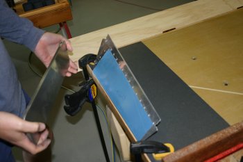 |
| Well I ended up being annoyed at myself, if you do the same thing, even being careful both times you end up with the same result! Difficult to tell in the photo but the skin is bowed in the centre AGAIN! | 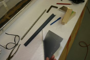 |
| After calming down a bit, we decided to make a Mark II bending brake - this time a steel piano hinge was used. This worked better and we managed to get a reasonable crimp, although the ends still have a little flare, we moved on to the next step. | 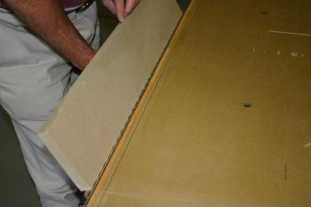 |
| Then it was the outboard tab end. I realised yesterday's wedge was incorrectly measured so I made a new one as I thought this might be causing the problems of marking / denting on the skins. Once the wedge blocks are clamp down the bow becomes even more pronounced. | 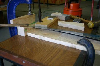 |
| Then I used a mixture of wooden block, AL drift and small bucking bar to shape the lower tab. The resultant line is fairly straight and it looks OK. | 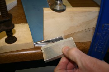 |
| The problem was then the tab rubbed against the upper skin, so I had to thread a piece of sand paper to remove some of the flange towards the tip. My advice for anyone else is be fairly generous with the trimming / sanding of the lower tab tip. It is a very slow process once it is bent. | 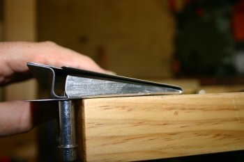 |
| Then it is a flip over and do the upper skin. This came out fine, although the tip is a little close so the fold isn't as neat as I would have liked. If I was doing it again, I would move the bend slight further towards the end of the trim tab. | 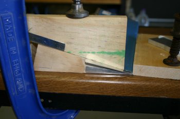 |
| I then moved round to the inboard end. I started with the same wedge but I realised before clamping where some of the dents had come from yesterday. | 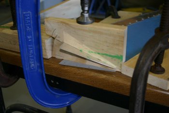 |
| I'll try to explain - the 16 ish degree angle is perpendicular to the trailing edge (not the leading edge) but the wedge has to be rotated for the inboard tab. This leaves an outboard side of the wedge below the skin level. The problem then comes if a large support (eg the upper part of the wedge) is clamped above the wedge and it forces the skin around some 'bad' edges. This then results in the dents. | 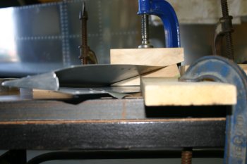 |
| Once I understood the problem, I then set about trying to fabricate an 'improved' wedge that didn't have this problem. The problem with the new wedge is it is a compound shape (ie multiple non perpendicular edges). Therefore I'll try and explain how I got to something that worked. | 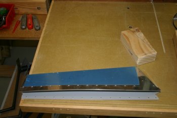 |
| Take a single largish block of wood. Get 4 square edges and mark one as the reference. Then duplicate the bend angle from the skin to the block. | 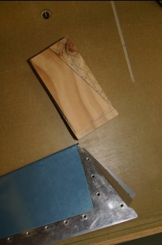 |
| Then you have to make the 16 degree cut from the lower surface top edge (top left in the picture) to the upper rearward surface (lower right edge). | 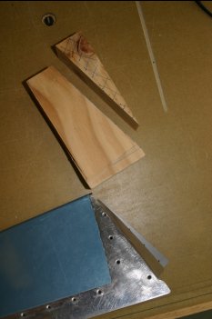 |
| The two left block are after the cut, the middle block being rotated by 90 degrees. | 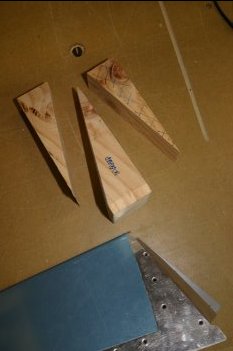 |
| Then as I had already dimpled the skin (pre-priming) I marked and counter sunk the wedge in the appropriate locations. Here you can see the wedge right way up ready to go back into the skin. | 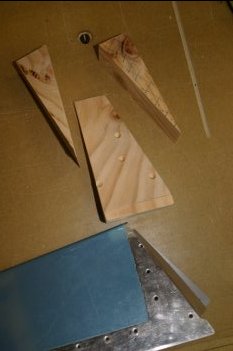 |
| The new wedge is flush along the bend line. | 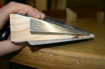 |
| But also fills the skin angle correctly and therefore provides the proper support for clamping. | 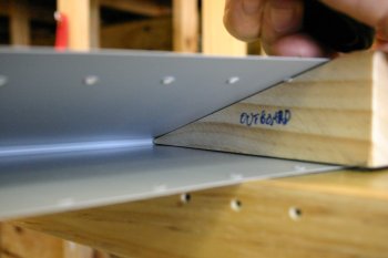 |
| Here you can see the original and new versions of the wedge. The one on the right was used from this point on and worked quite well. | 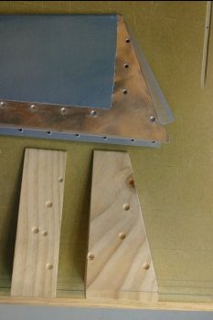 |
| So with the new version, I went back to forming the lower tab bend on the inboard end. | 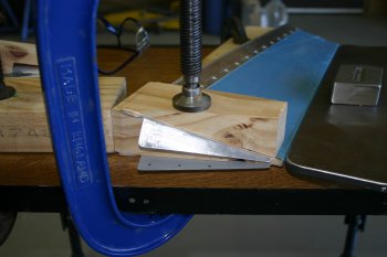 |
| The result - a nice crisp clean line bend - the best yet. Again the lower tab was a little too big (this was after some additional trimming but it all worked OK). | 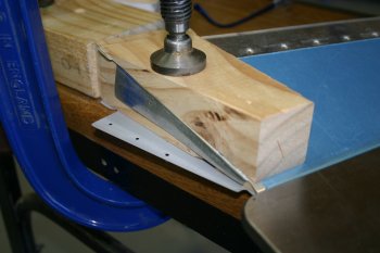 |
| Then flip over and do the upper surface. I helped support the upper wedge from slipping with some masking tape doubled back on itself. Then the normal range of weapons for do the actual forming. | 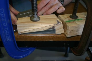 |
| The finished inboard end. Not too bad, although there are still some slight marks on the skins where the upper support overlapped the lower wedge. Other people will be hard pressed to find it, but I know it is there! | 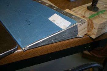 |
| The final step of drilling for the trim tab is the control horn, just a cleco on and match drill a few holes. I finished there for the day. Tomorrow I guess it will have to be the left elevator tab bending - what fun..... | 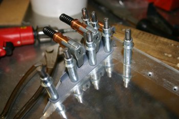 |
| Some summary thoughts. I wish all builders the best of luck with this part of the project! I'm not sure if we are being overly cautious, paranoid, picky, unlucky or stupid. So far this has been the most difficult piece of the project in terms of getting a result that I'm really happy with. I guess I'm being a perfectionist but I've generally found worst case by the second attempt at something I've got the hang of the techniques needed. This is not the case with the trim tab bending. I ordered an extra skin (which I'm really glad I did) and practiced on that, and even now with what I suspect is a perfectly fine trim tab (functionally and aesthetically) I'm still not particularly happy with it. Until I've finished dimpling and riveting the part together, and then presenting it up against the elevator trailing edge I won't know for sure whether the bowing and problems will all evaporate. The kit is so well designed that I suspect it will work out and I'll just get to a point and move on, we will see. I'll also be far more interested in looking at other RV trim tabs..... With regard to the instructions from VANs, I'm not sure if I just didn't interprete them well enough or (what I think might be the case) as the new empennage kits now don't require any jigging the skin formers that used to be readily available / constructed (and the drawings to go with them) are now only being needed for tab bending. I'm struggling to get tools accurate enough when the comments are 'create a wodden block' but no angles / dimensions are given. This leads to damage of parts which isn't really necessary but difficult to aviod as a first time builder. | |
Fri 27 February 2004 | |
| The day started with some simple cleanup and dimpling of the trim tab components. | 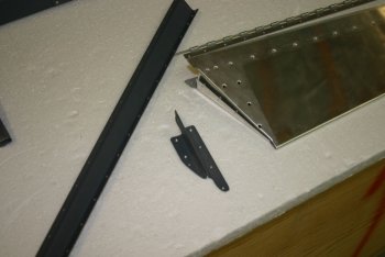 |
| I then marked out and drilled the servo mount for the electric elevator trim. | 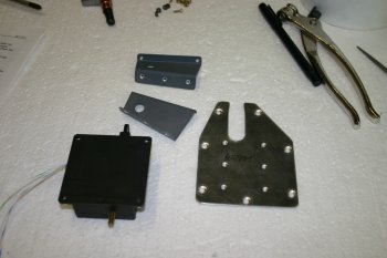 |
| The above parts plus the trim hinge needed priming and the wind wasn't too bad so I took the opportunity to clean, etch and prime. One of the advantages of rattle cans. | 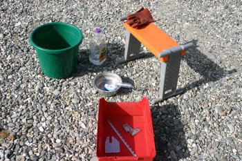 |
| Up to this point the trim tab had gone OK. The riveting of the trim horn however didn't go well. The penultimate aft rivet had to be bucked, but the gun slipped and put a small dent in the skin. | 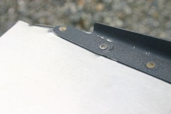 |
| The aft most rivet however was even worse. The only option we could use for bucking is the back riveting bar, this is not a good thing to try unless the rivet is fully on the bar. As we found out it puts dents in the skin (AGAIN!). I sent a question to the email list, although I expect the general answer will be 'pop rivet' it, we will see. | 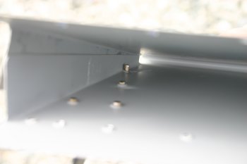 |
| Then it was onto the elevator and the bending of the tabs. The first step was to make another compound wedge. | 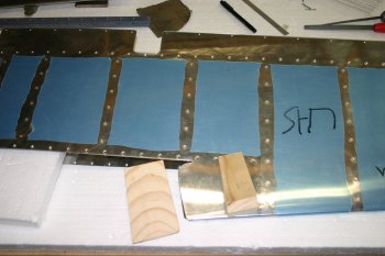 |
| This was then clamped and shaped with a wooden block. The result came out well with a clean bend line. | 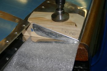 |
| The tab was still too big, even after trimming so more filing & sandpaper. | 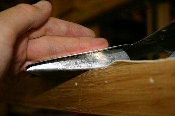 |
| This is how we have been fixing the wedges into the skins. A loop of compound tape all the way round helps hold the wedge inside the skin tightly. | 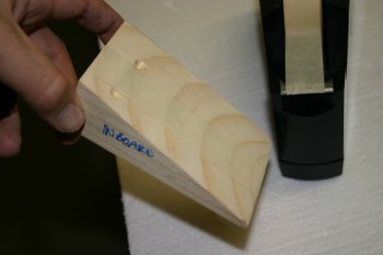 |
| With all the trimming done, flip the skin and setup for the top tab. The bend went well - 10th bend was the first one that looked and worked really well. Oh well the next project will be easier. | 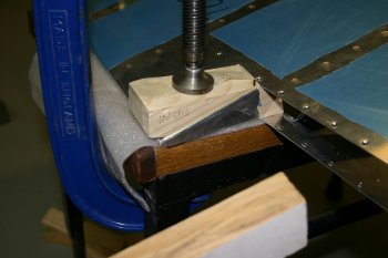 |
| I mocked up the elevator & trim tab. The finished trailing edge was reasonable but the inboard end of the trim seemed a little high. I'll wait until the elevator is riveted together to work out if the trim tab is a problem. |  |
| The overall look of the left elevator. Lots of stress and hassle for that little (important) bit. | 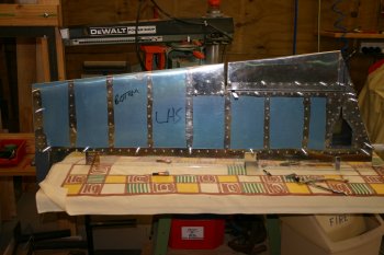 |
| This is the trim tab / elevator gap. It 'should' be parallel. It is difficult to tell until the tabs are riveted together and that needs to wait until after the elevator skin is riveted unto its skeleton, which in turn needs the pro-seal........ Wednesday we should get the pro-seal!, until then - something else will be on the todo list. | 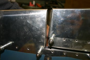 |
Sat 06 March 2004 | |
| Then back to the elevator trim tab. You may recall that I had problems with the aft most rivet on the trim horn. The overwhelming response on the list was pop'em and move on. I decided to use a MK-319-BS rivet which has a AD3 countersunk head (rather than a CS-4-4 with an AD4 head). | 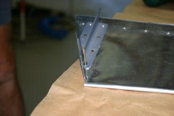 |
| The MK-319-BS rivets have a diameter of 7/64", therefore a standard #40 drill isn't big enough. We ended up using a #34 drill which was a nice snug fit. The finished results looks fine. Next time I would start with the pop rivet option. | 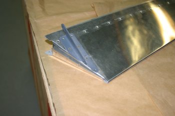 |
| With the new knowledge about the M-319-BS rivets, I noticed the rear spar of the left elevator also uses these rivets for the outboard locations. I match drilled these to #34 also before we moved on to the black death stage.... | 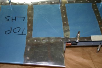 |
| Then it was time to start the Pro-Seal fun and games. | 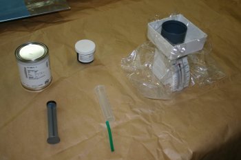 |
| We started with the elevators. Took all the skeleton structure out of them and removed the dust from the internal corners. | 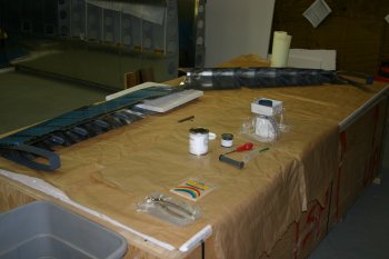 |
| Dad then starting the mixing process, 10:1 by weight. We ended up with about 3 ounces of mixture which just did both elevators. | 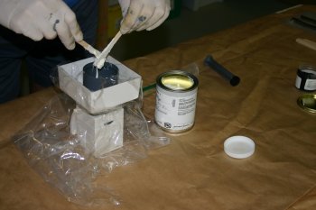 |
| The blob of goo was put between each pair of stiffeners. | 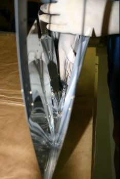 |
| The two elevators didn't take that long to complete. After the goo was in, the skeleton was re-cleco'd together and we left them standing vertically for about an hour to let the Pro-Seal settle a little before setting. Tomorrow I'll try to finish off the riveting. | 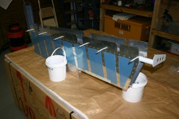 |
Sun 07 March 2004 | |
| Then it was back to the elevators. I started with the right hand side and removed the skeleton so the lead weight can be located. | 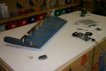 |
| The Pro-Seal was still fairly sticky so I tried to not flex the skins more than needed. | 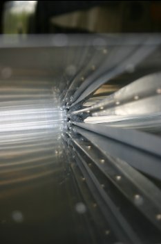 |
| Then re-aligned everything and cleco'd both sides thoroughly. | 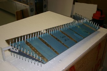 |
| I then started the riveting process, starting at the forward end of the counter weight, alternating top and bottom surfaces. The outboard end was completed first, then the leading edge (top and bottom). | 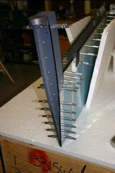 |
| Finishing with the inboard edge (spar to trailing edge). End result was good with only the rolling of the leading edge left to do. | 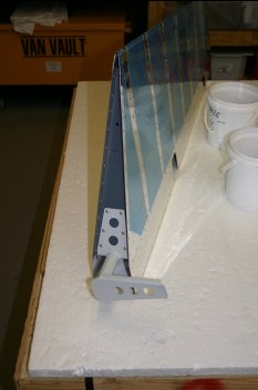 |
| Then left hand elevator. Same principles applied. | 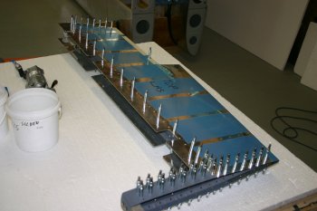 |
| However I set the 8 MK-319-BS pop rivets on the trailing edge spar before working on the solid rivets. | 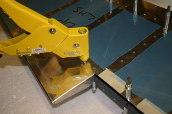 |
| Same process, outboard leading to trailing, leading edge spar, to trailing tip of inboard edge. | 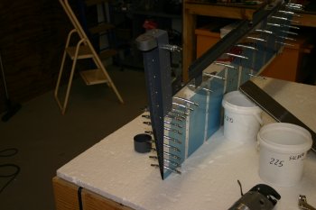 |
| Then set the two AD3 rivets for the tailing edge spar. These are AN426's so it would have been easier to dimple before assembly (HINT). | 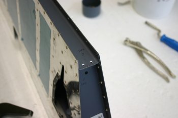 |
| The final part for today was back to the elevator trim tab. | 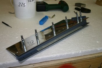 |
| We aligned the trailing edge and upper surfaces with a couple of straight edges and clamped the piano hinge. | 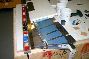 |
| The gap between the trim and the elevator skin has to be a minimum of 3/32" which isn't a huge distance, but we still have the V shaped gap. | 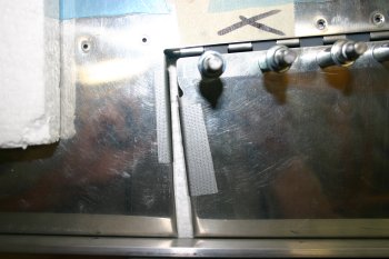 |
| I drilled and pop'd the elevator tabs to assist with the alignment process. | 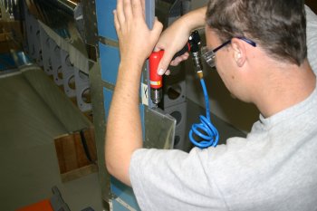 |
| Then the hinge was drilled in one of the mid locations to provide better line up. | 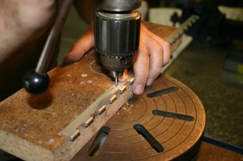 |
| VANs talk of being able to change the 'twist' in trim tab with the pop rivets in the ends being set to hold the twist. We set just the one at each end however this didn't seem to work particularly well but a little variation was possible. | 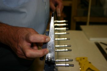 |
| Then I riveted the upper side of the trim tab spar. | 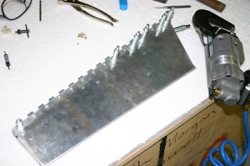 |
| And remounted the trim. The final position hasn't been fixed yet, I'll look at the drilling again tomorrow. I think I may have made a mistake with the trimming of the piano hinge which may mean I need some work P2 hinge. I'm still not very happy with the whole trim tab part, I will consider if I should order a replacement from VANs when I next have a shipment being sent, the idea of being reminded EVERY pre-flight of something I'm not 100% happy with may be enough 'justification' for another try at this part. I also managed to spray one side of the bench legs plus some other tidying items. | 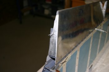 |
Mon 08 March 2004 | |
| This is the hinge on the elevator for the trim tab (inboard end) - it is too short. Therefore I'll need to order some addition P2 hinge before we can complete the left elevator. | 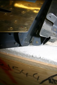 |
Sun 28 March 2004 | |
 | |
Sat 18 December 2004 | |
| Then the elevator tips, these needed a lot of trim and the fit is quite tight, I suspect I will end up making the fit easier and then using micro-balloon filler to cover up the gaps / provide a nice smooth transition from metal to glass. | 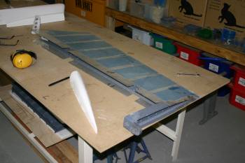 |
| The major obsticle is the lead counter weight. If I had know (/ thought of) the tip fitting at the front, I would have notched the lead to provide space for the upper / lower tip surfaces. Oh well, I'm sure I'll come up with something. Had another local builder visit which was interesting to find out what engine options / toys he is going with, rest of the day was helping in the garden again......... | 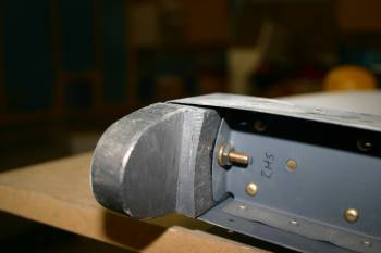 |
Sun 19 December 2004 | |
| Another bitty day, the lead weight problem I just cut round. Works OK but if you haven't sealed the weights into the elevator structure, do some trimming of it first to make the tip fitting easy! | 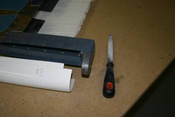 |
| Then it was drilling the tips and shaping | 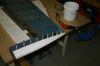 |
| I also sorted the other tip | 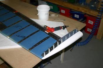 |
Mon 27 December 2004 | |
| To finish we went back to something we have been putting off for a while, elevator leading edge rolling. | 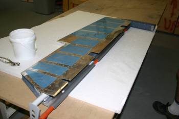 |
| We manage to sort one of the outboard ends, stilling having problems getting an even curve / bend. Will need to sort tomorrow so the HS / elevator pivots can be done. | 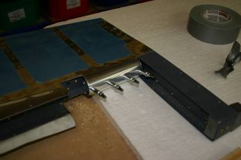 |
Tue 28 December 2004 | |
| Continued with elevator leading edge. Manage to identify a piece of plastic tube / wood core that didn't bend / flex / twist. Then added a couple of bolts as tommy bars to increase the leverage. | 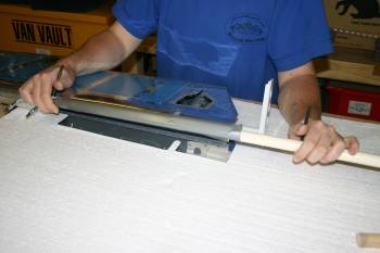 |
| After quite a bit of effort, we had the whole LE cleco'd together. Seems to be the 'best' method was to work with the separate sections one at a time and have one person providing the 'torque' on the tube and the other working the material by hand. With a bit of confidence it did end up going OK. | 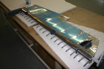 |
| The drill and pop-rivet was VERY simple in comparison. | 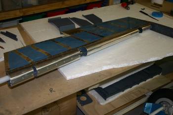 |
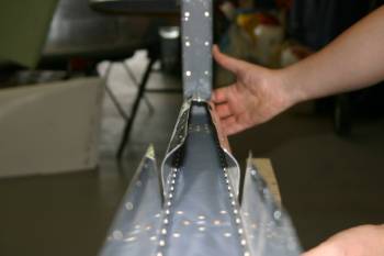
| Both of us were then back so we returned to the RHS elevator LE rolling. The little outboard edge rolled first time, the middle one was a real pig. | 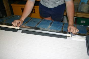 |
| You can see the principle, generally the meeting point is flat with a rolled component and then arcing to the spar. The trick is to not crease the skin along the spar line. | 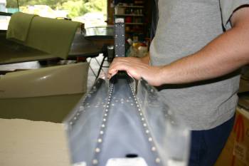 |
 | |
| Then it is the normal drill, debur | 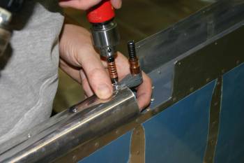 |
| and pop-rivet. | 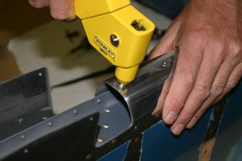 |
| The second finished product, added the rod end bearings and started looking at the mounting to the HS. The HS skin will need trimming, a job for tomorrow. | 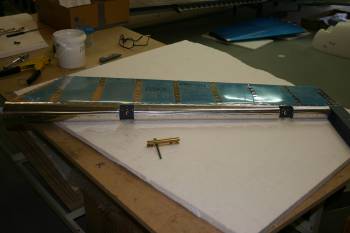 |
Thu 30 December 2004 | |
 | |
 | |
 | |
 | |
 | |
Tue 22 November 2005 | |
| The inside of the elevators ribs in particular are very tight with the tips. 'Next time' I would trim them back before riveting. We just reshaped the tips slightly and moved on.... | 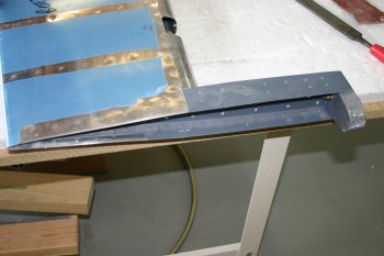 |
| Then I masked up all the edges 1/2" away - this will be used to feather the micro-balloons down to provide a neat straight edge. I used a piece of masking tape as the base layer and electric tape as the main 'protection'. A good scuff / sand roughens the surfaces to help the silica / epoxy past stick. I also trimmed the forward edge of the lead counter weights which had been missed to date. | 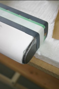 |
| With the elevator aft most rivets we ended up using AD3 blind rivets - even then it was really tight. | 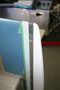 |
Wed 23 November 2005 | |
| Still looking for things to do - we were left with the THIRD elevator trim tab. The previous results have been patchy - the second attempt was OK but the alignment of the edges and hinge wasn't great. This time we decided to do things slightly differently, instead of bending the end tabs after 'crimping' the trailing edge we removed the lower tabs and will re-make these later. | 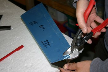 |
| Then we pre-bent the upper tabs. | 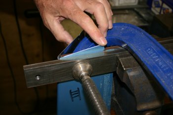 |
| This was the result ready for the bending brake. | 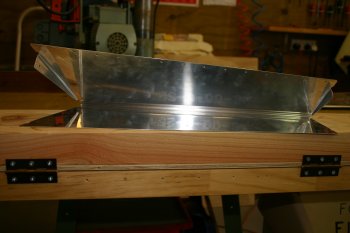 |
| With the brake we held the front edge and 'with confidence' flattened it. Worked well, maybe slight pinched but good enough. | 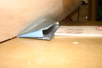 |
| Then it was process the mini-spar etc, the hinge pin alignment look OK but it was getting late so we didn't drill too much. That can wait for a fresh review tomorrow. All in all a good productive day, and hopefully tomorrow should be delivery day - lots of bits, lots of options on next steps. | 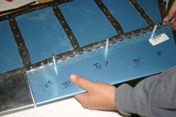 |
Thu 24 November 2005 | |
| I started by rough sanding the end counter weights of the elevators. 60 grit sand paper on the palm sander removed some of the really high peaks, then 100 grit by hand. | 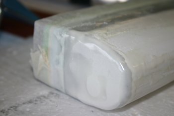 |
| Then started work on the upper / lower intersections. The idea is to slowly remove the micro-balloon filler down to the electrical tape - this provides a clean edge to the filler and the surface should be good and smooth all over. | 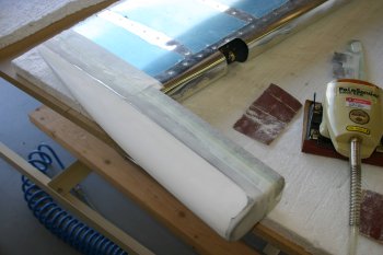 |
| After a couple of hours of sanding, Dad got home and we returned to the elevator trim tab. The key piece was the drilling of the hinge for the elevator. In hindsight I positioned the rear section too far forward, this meant the edge distance is very tight on the elevator. After some careful layout it did all work in the end. | 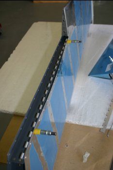 |
| Then I went on to make the trim tab end 'half-ribs' and Dad deburred and counter-sunk the mini-spar. NB: Only the top of the spar needs to be counter-sunk! | 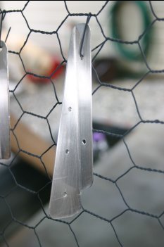 |
| Then it was edge, scuff, etch and prime. | 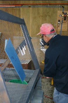 |
| I returned to the elevators - lots more sanding and shaping - slow iterative stuff. Once I was getting close I removed the electrical tape (just the green masking tape left) and feathered further. This is only a first cut - at least one more micro-balloon session will be required and then probably filler/primer compound. The end result should be completely smooth with no visible joint. | 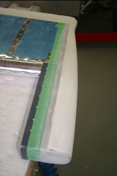 |
Fri 25 November 2005 | |
| Dad continued with the trim tab dimpling and countersinking as needed. I did another side of sanding micro-balloons on one of the elevators. | 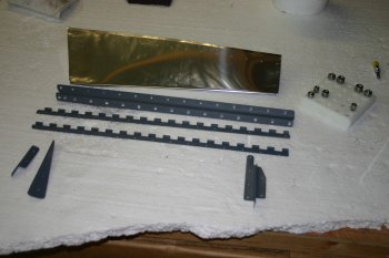 |
| Then back to finishing the trim tab. | 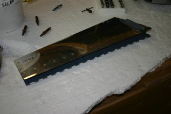 |
| This is a close up of the end half-rib that we added. | 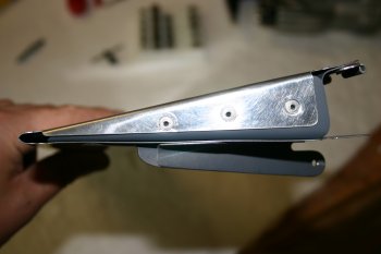 |
| And the hinge bracket on the elevator - end result looks good | 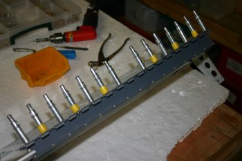 |
Sat 28 January 2006 | |
| Using a microballoon based thickish mix, we layered the mix on and let gravity and surface tension help the levelling process. | 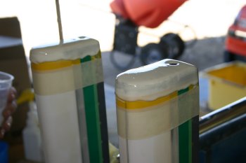 |
| The peel-ply with baking sheet and AL plate with a couple of bucking bars for pressure. We will see tomorrow if this has worked, but hopefully a smooth / flat surface will be left - in theory! | 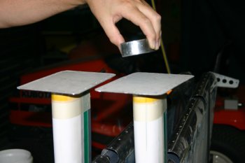 |
Sun 29 January 2006 | |
| The elevator counter balance peel ply came off cleanly, maybe not quite enough in total but a good start. I left it to cure before starting any sanding. | 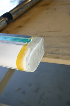 |
Mon 13 February 2006 | |
| Then onto some sanding (for a change!). The elevators still needed the counter balance to be sorted, palm sander worked well. |  |
| A bit job that has been on the list for a little while was the elevator trim push rod. I could find no dimensions / drawings detailing lengths so went with the mark one eyeball. One note, the servo end has to be connected before it is put into the elevator - otherwise there isn't any access. |  |
Tue 20 June 2006 | |
| I ended up with too much mico-balloons so I filled the ends of the counter-balanaces on the elevators. | 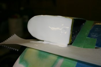 |
Tue 27 June 2006 | |
| Started today by tidying up and sanding flat the elevator couter weights | 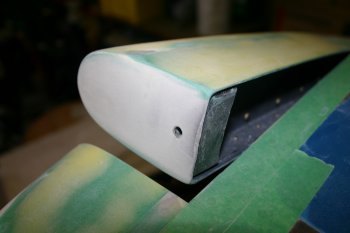 |
Mon 03 July 2006 | |
| A bits day, among other things I sorted the trim servo wiring and some shaping of the access panels. | 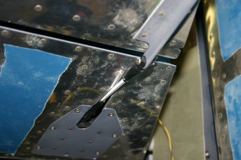 |
Fri 02 February 2007 | |
 | |
Sun 03 June 2007 | |
| I also shaped and worked on the elevator trim tab push rod clearances. | 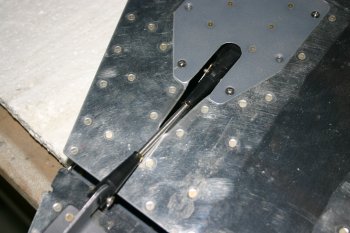 |
Sun 05 August 2007 | |
| Dad worked on the elevator balancing - this is the 'washer' that goes on the aft side of the elevator tips. | 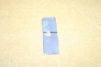 |
| The LHS elevator needed about 15 grams to get to neutral, the RHS is still slightly nose heavy. | 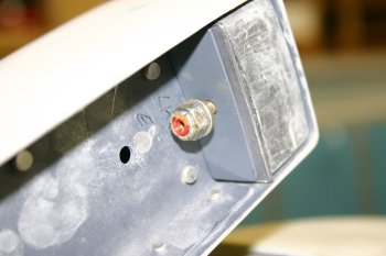 |
Mon 06 August 2007 | |
| The RHS nose heavy elevator was drilled out a little - although after a few questions / thought we decided to not quite full balance as we expect the paint to need more on the nose. | 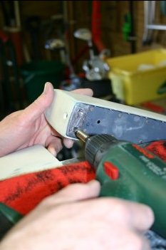 |
| Then it was bolt everything up and torque seal. | 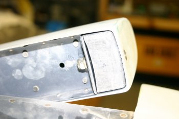 |
Fri 10 August 2007 | |
| Push rod alignment and final tightening of the various assemblies. | 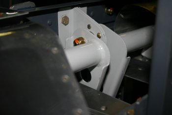 |
Sat 11 August 2007 | |
| Setup and locking things down. Clearance on the servo is tight - but fine. | 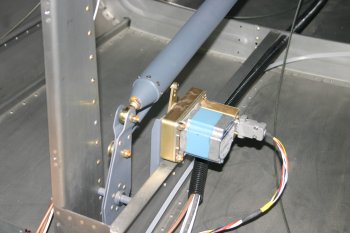 |
Sun 12 August 2007 | |
| Dad finished the elevator rigging / spacers for the main push rod. | 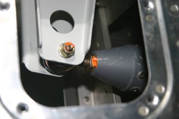 |
| Home | Carl Morgan | Previous|Next|Latest |