Horizontal Stabiliser |
|
| First part of real construction of the project. Not a huge deal of progress made, but psychologically an important step. I was starting to feel quite frustrated that each day we were improving the shed working environment, eg racking, shelving, benches etc all of which is important, but I wasn't actually working on the plane. The rear spar was cleco'd together and match drilled. | 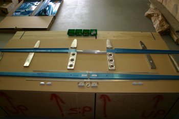
|
|
| More thinking time & understanding of the instructions / drawings for the Horizontal Stabiliser. At this point I'm taking these pretty cautiously and trying to get a good methodology going. Later on I hope it will pay dividends. | 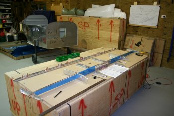
|
|
| Deburred and smoothed all the edges of the HS parts excluding the skins. Also sanded down the front HS reinforcement bars ready for bending - really pleased with the finish. | 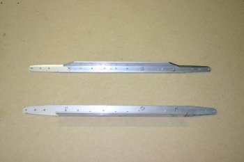
|
|
| The front spar of the Horz Stab is common between the RV 7 and 8. The RV7 has to be slightly modified. | 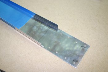
|
| First we drilled the #30 pilot holes | 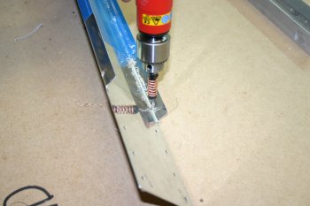
|
| Then opened up the edges to the 1/4" using the uni-bit | 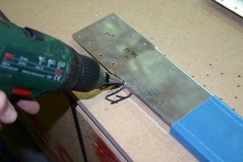
|
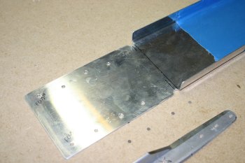
| The finished product ready for bending to the magic 6 degree line along with the spar angle stiffeners.
| 
|
| The method we used to bend the front HS angle stiffeners. They did require quite a firm hit, about 3 - 4 times. The problem was if you didn't hit it hard enough the material started to work harden which meant you then had to hit it even harder. Mainly preparation time and getting everything lined up. | 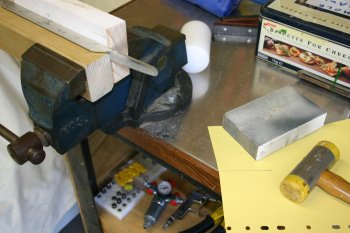
|
| We next fluted all the HS ribs and cleaned up the parts. This is all the HS internal parts together ready for the skin to be cleco'd on so that we can complete the match drilling. | 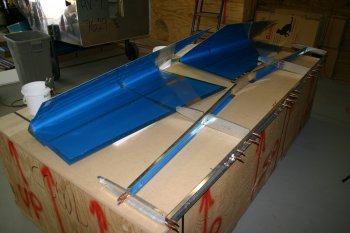
|
| The finished cleco'd complete HS structure. We struggled with the front nose ribs and it needed some gentle 'persuasion'.
We drilled out the #19 rib holes on the rear spar. It was after dinner time so we called it a day. | 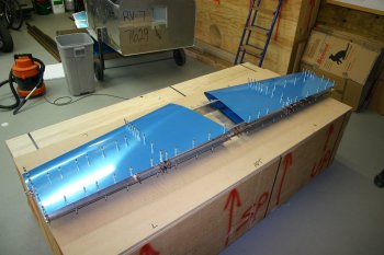
|
|
| The front spar of the HS presents several things for the new builder to work on. One of the 'challenges' is the line up and drilling of the four holes through the inboard web and rib in conjunction with the front spar and the 2 reinforcement bars. The drawings are a little lacking (if we are being generous) with most of the dimensions given being of limited use. | 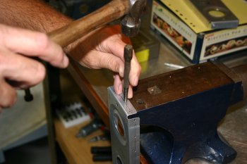
|
| This was our best second guess (the first one was slight off), and it ended up with 1/4 inch in from the edges and 1 1/8 from the flange ends although I think now a slightly reduced distance for the mid - upper hole in for the front rib would be better. | 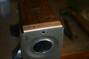
|
| We then used #40 pilot drills with an angle drill adapter to match drill from the aft side forward. | 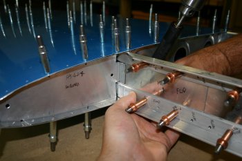
|
| Both the upper and lower reinforcement angle need to be held firmly by hand whilst drilling forward as they have no fix further outboard at this point in the process. Just watch out for the fingers..... | 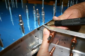
|
| We then cleco'd the top and bottom holes and moved onto the forward rib holes. Again we drilled from the aft side forward as instructed, but it is a little difficult to know where you are going to end up. Drill clearance is also very tight even with an angle adapter. | 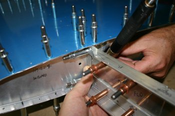
|
| The final stage is to drill back towards the aft end of the HS with a #30 drill. | 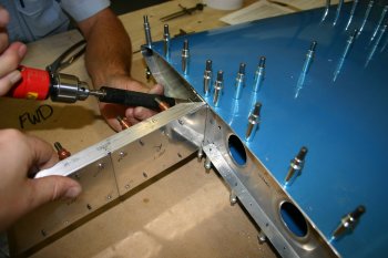
|
| The finished product, not quite perfect but sufficient for the needs of this step. Just makes you realise how 'spoilt' we are with the modern VANs kits and all the pre-punched CNC'd holes. I sometimes think a well cleco'd aircraft would be a bit draggy but still fly...... | 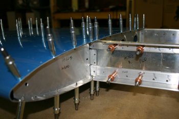
|
| We then went round drilling out all the skins to the required #40 ready for deburring and dimpling. | 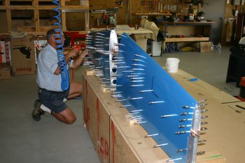
|
| I then started the deburring and dimpling. Manage to get a few HS pieces done before packing up for the day. | 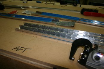
|
|
| Started the day continuing with the deburring and dimpling of the spar and internal elements of the HS. | 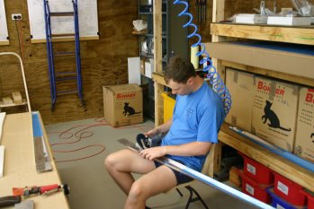
|
| The dimpling of the front 3 rivets in the HS-601 skins was a bit tight so we used the pop rivet with holey dies. Worked well and meant we didn't need to stretch the skins too much. | 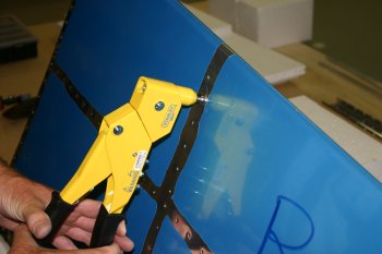
|
| We then finished the skins with the C frame dimpler. Apart from the edges of the skins the HS is now done and ready for priming. One gotcha to watch out for, the intersections of the skin, HS-702 spar and main ribs are 3 layers of material, therefore the middle layer (the spar) should be counter sunk and not dimpled - don't ask how I know ;-). | 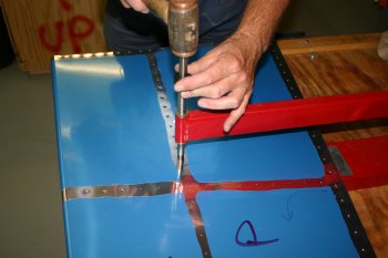
|
|
| Finished cleaning up all the edges, deburing the holes and finishing the HS skins. HS ready for priming, added the parts to the pile. | |
|
| Next I riveted the Horz Stab central bearing, this is normally the first assembly to be built. | 
|
| I found the AD4-5 rivets suggested too small and used AD4-6 for 4 of the 6 holes. | 
|
|
| Then we moved on to the horizontal stabiliser. Firstly I wanted to drill the #12 holes for the central bearing but the parts didn't seem to sit properly. | 
|
| Therefore I took the step to drill out all the rivets and start from scratch again. (Hint: A AN4 nut works well as a drift female for removing bat AD4's) | 
|
| Dad also did the red-oxide the steel HS parts that have exposed metal. | 
|
| I decided to remove the recesses for the elevator control horns before riveting the spar together. This would have been possible later, but much harder to complete without causing other damage. | 
|
| Then it was cleco the spar together and squeezer from centre to tips. | 
|
| It all came together nicely and then we bolted and verified the centre bracket was in proper alignment. The second riveting attempt went much better. | 
|
| We then moved onto the forward spar. In slight variation from the plans we haven't riveted the front inner rib on at this point. It is only the two inner rivets and we used it to help form the skin shape (see below). | 
|
| Next up is the skin. The instructions call out for just the upper skin and then the lower skin to be riveted at the forward mid rib. We decided to cleco both the end ribs into the structure along with both sides of the mid rib. This then meant the whole airfoil shape was completely formed and made bucking the shape easier. The rib was bucked top and bottom working from the forward spar to the leading edge. | 
|
|
| Then it was back to the horizontal stabiliser. I riveted the inner front rib to the front spar. | 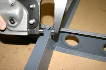
|
| And the end rib to the spar. | 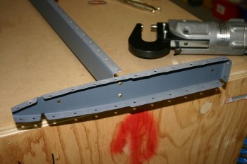
|
| Dad joined me after dinner and we completed the bucking on the mid rib on the right hand skin. | 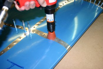
|
| We then cleco'd up the front spar onto the skins and blind riveted the spar to mid web / ribs. | 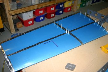
|
| By the end of the evening we had finished the spar to lower skin surfaces. Upper surfaces tomorrow. | 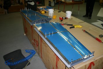
|
|
| We started by finishing off the HS skins. Normal bucking routine. | 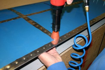
|
| The next step is the rear spar. We are currently waiting for some more rattle can primer which I need to fix a couple of things before the rear spar can be attached. | 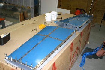
|
| Therefore, we hung up the HS for safe keeping and moved onto other things. Probably only a couple of hours to complete once we have the materials. | 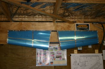
|
|
| Mid morning the rattle can primer was delivered so I could go back to the Horz Stab. I finished the rear spar spraying and remounted the hinge brackets. | 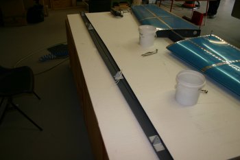
|
| Then I did both end ribs, leading edge to spar, top and bottom. | 
|
| Then the mid section, tip to spar again. | 
|
| Then the rear spar. I decided to lock the mid and end ribs / spar with the AD4 rivets before doing the skin to spar parts. | 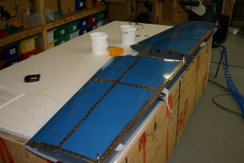
|
| For the skin to spar I started at the HS708 mid web and worked towards the centre on both sides top & bottom and then the HS708 / spar outboard. Seemed to work well. | 
|
| The final step of the process is to set the two blind pop rivets to hold the 708 to the rear spar. | 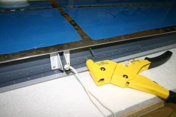
|
| The finished assembly. The only remaining work is the fibreglass tips, painting, mounting......... (and more that I'm sure we will come across). | 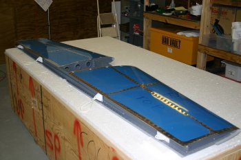
|
| Safely stored for future use. | 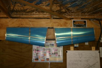
|
|
| The HS tips needed a little triming, so that was sorted first up. | 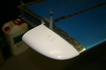
|
|
| A short day as we had errands to run this morning. First up Dad checked the HS alignment. After re-reading the instructions the 'simple' option was to just put the 3/16" drill under the rear spar and drill, the extra check was the tooling holes should be the same height from the rear deck. Surprise, surprise follow the instructions, and it all works fine. | 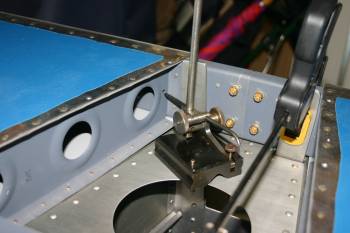
|
| With everything lined up the drilling could start. We started with pilot drills and then worked up the sizes. | 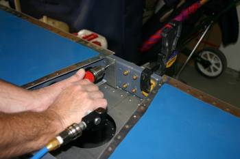
|
| The HS was rechecked frequently for level / alignment. | 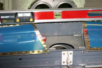
|
| #30s from the front, | 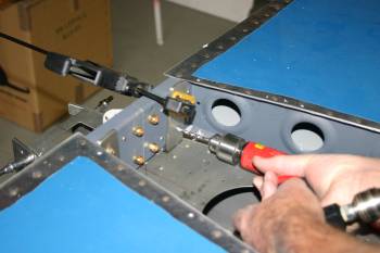
|
| then final 3/16s from the back. | 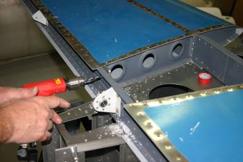
|
|
| The mounting of the elevators on the HS is pretty fiddly but otherwise not too hard, first looks were good, but it became obvious quickly that multiple on and off operations were going to be needed so we removed the HS to the bench. | 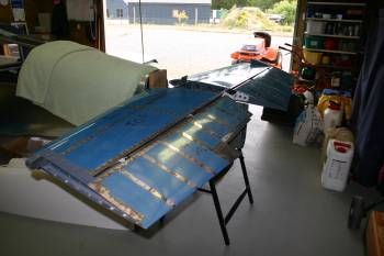
|
| The second observation was the RHS elevator horn seems to be at an angle to the center bearing (more later) | 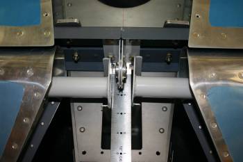
|
| The bench was a good plan, generally we used shorter make up bolts during the test fitting, although a pair of long nosed pliers was still needed. | 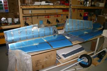
|
| Early on the trimming of the HS skin was needed, we started with the lower surface and did the upper surface after the center bear drilling (see below). Normal type of drill, rough cut then file and finish. In round term it is just under an inch of skin from the trailing edge of the mid spar. | 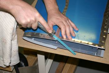
|
| The alignment of the two elevators was a slow and iterative process. A half turn of the pivot knuckle changes the hinge point by 1/128". The center of bolt to spar is a min of 13/16" and a max of 7/8" - a whole 1/16" to play in (ie. about 3 different orientations)! Also the clearance of the rolled leading edge and horn bolt spacing all have to be taken into account. | 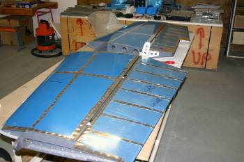
|
| Got there in the end with everything looking good. The HS lower spar flange needed a little additional trimming and the gap looked a bit one sided, but everything fitted snugly and rotated freely. | 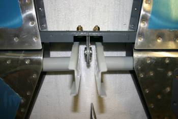
|
| Dad made a bushing guide for the 1/4" bearing with a #40 drill center, fairly simple once everything is setup, just drill into each horn in turn. | 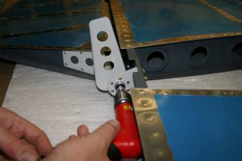
|
| Then it is open to 1/4", debur etc. | 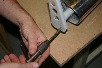
|
| And re-assemble. Everything fitted well and all rotated without issue. | 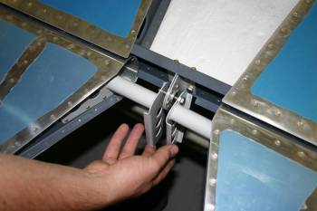
|
| The problem is the RHS bearing to horn is still too large, the drawings state 3 washers max and it needs about 5! Not sure what - if anything went wrong, probably just the weldment. Email to VANs tonight, not sure if they are working over the festive season but hopefully we can get a solution and move on. Plenty of other things to do in the mean time. | 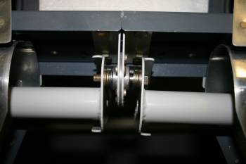
|
|
| | 
|
| | 
|
|
| Continuing with the HS I drilled and marked up the tips, | 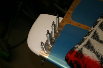
|
| and trimmed the excess material. | 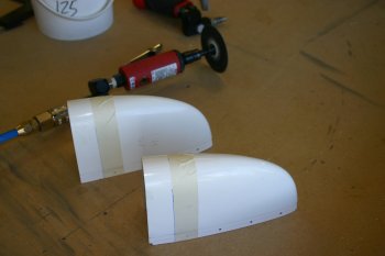
|
| We also mounted the elevators and rudder control surfaces. | 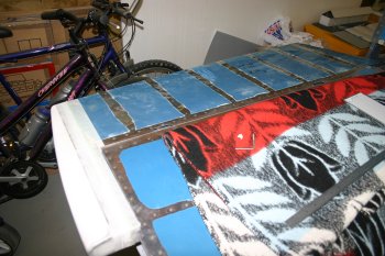
|
|
| I worked on the HS tips. Using some form to form a backing support. | 
|
| Then a bead of silca / flox around the edges, | 
|
| and two layers of 2oz BID cloth. This was then left in the sun to cure. | 
|
| Finishing off, after a few hours the glass work had started to harden, I used a knife to trim the excess BID cloth and then left well alone for it cure. The plan is to put another layer of cloth on the inner side after removing the foam. | 
|
|
| I used some of the left over flox to stiffen the edge of the HS tips. | 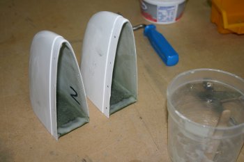
|
|
| In preparation for tomorrow, I also de-rigged the HS for Dad. | 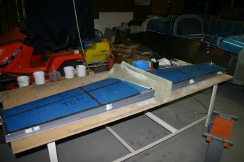
|
|
| The HS tips were pop-riveted on with flox under the joint and a small amount of micro-balloons was added for the initial filling / shaping. | 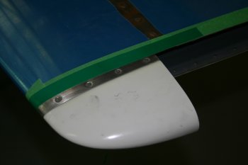
|
|
| Also sanded back the HS tips for the elevator clearance, maybe a little more to complete, but good enough for the moment. | 
|


