


 |
 |
 |
| Home | Research | Delivery | Empennage | Wings | Fuselage | Finish | Engine | Electrical | GRTDecode | Previous|Next|Latest |
| Wings | Left Wing | Right Wing | |
Right Wing | |
Sun 18 January 2004 | |
| Whilst Dad was working on the wing cradle, I got started with the Duckworks leading edge lights. We have two, one for each wing. I spent a couple of hours deburing, smoothing and edging all the various parts. | 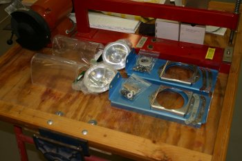 |
| All the paper templates were copied and strengthened with card. Then cut to the appropriate sizes and shapes. | 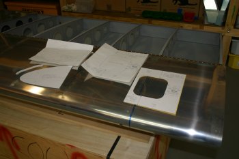 |
| The template location was measured carefully. Cutting into the pristine completed leading edge is rather daunting. | 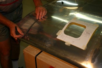 |
| Right wing light location all masked up ready for cutting. A job for tomorrow after some sleep. | 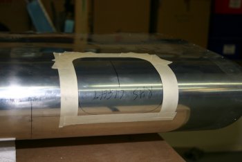 |
Mon 19 January 2004 | |
| The first item of the day was to cut into the leading edge of the right wing and then shape the hole to the template. The initial cut was done with a sabre saw which gave this type of hole. I'm sure with more practice I could be more accurate, but I was being cautious. The second phase of shaping I used a rotary burr in a die grinder. This is a fairly vicious tool for removing material but seems to work quite well.
I then moved onto doing the same on the left wing. | 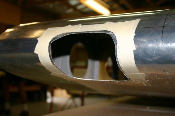 |
Tue 20 January 2004 | |
| Dad filed / cleaned the edges of the right wing landing light hole. | 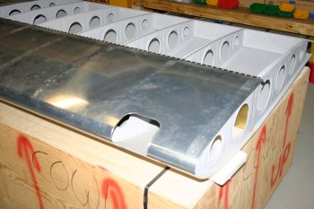 |
Fri 23 January 2004 | |
| Today I focused on the landing light Plexiglass. Plexiglass is a strange material that holds its own complexities. It is easy to crack and requires another new set of skills to work with. First I covered the plexiglass with masking tape to stop scratches and marks. Then it was then taped to the front of the leading edge and a bright light was shone from behind to illuminate the hole in the wing. This provided the shape for marking the front of the plexiglass. | 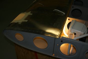 |
| Cutting the plexiglass is something that I haven't done before. I setup the die grinder with a simple cutting disk borrowed from the canopy finishing kit. It was actually easier than I expected and the finish of the cut came out well. I took it in multiple small steps and reduced the size progressively. | 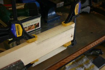 |
| Next I drilled the retaining plates. Starting in the centre and then cleco'ing as I drilled. There are two of these plates, one on the bottom (as shown) and one at the top of the wing skin. | 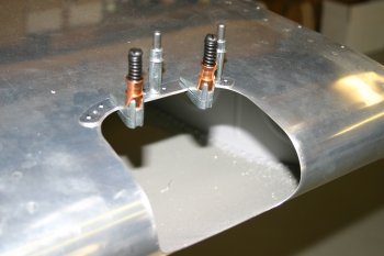 |
| Next we used a custom 1/8" drill for the plexiglass and these were then enlarged to 5/32" holes for clearance of the #6 retaining screws. | 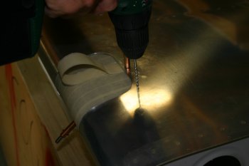 |
| Then more trimming of the Plexi, followed by careful sanding and deburing of the edges. | 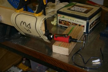 |
| Finally I finished up by match drilling and dimpling the wing skin, plates and nutplates ready for priming. | 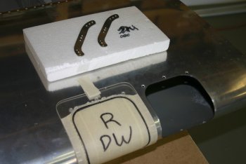 |
Thu 29 January 2004 | |
| Next up was mounting the braces and match drilling the parts to the wings. This is the flap brace for the right wing. | 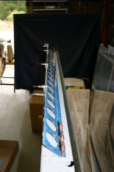 |
| Right wing aileron brace match drilling. | 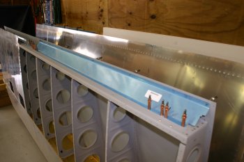 |
Fri 30 January 2004 | |
| The other problem was the lack of clearance to use the air drill to match drill the brackets (both outboard - as shown, and the platenut bolt on the inboard bracket). I decided before making a decision I would confer with Dad so I changed activities again. | 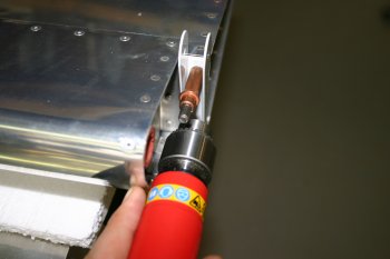 |
| Then I used the stubby drill in the rightangle attachment and completed the drilling on the aileron. If I find a solution I'm comfortable with we might get a completed sub assembly tomorrow (the first of the project) - a RHS aileron. Not quite the standard order, but I only have to put 5 bolts in and torque them up..... | 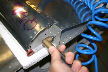 |
Sat 31 January 2004 | |
| The next sub-assembly I decided to look at was the basic TruTrak servo installation. This is going to be installed in the right wing and will provide the control input for the autopilot. The kit is fairly simple with a servo, two mounting brackets, a push rod and a spacer. It is a little frustrating that the 5 bolts, 5 washers and couple of nuts are not included in the US$2000+ kit. I guess I've got used to having a valid sub kit from manufactures, but it is frustrating to say the least to find something that can't be completed due to such simple problems AND will cost my US$40+ odd dollars just for the SHIPPING of the parts to NZ. There isn't even a callout for needed parts. I'm not the first person to complain about this and it seems a shame that what is meant to be a first class product is let down by something so trivial. | 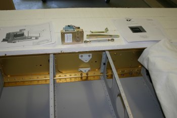 |
| I installed the lower TruTrak bracket. Removed, drilled the upper bracket and reinstalled with the bellcrank. I also removed, drilled and installed the bellcrank on the left wing. | 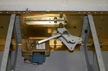 |
| Next up I started on the lower skin of the RHS wing. Normal process here, cleco'ing, drilling, deburring, dimpling etc. First though with the QB wings you need to remove the 4 (yes four - don't ask me how I know!) pop rivets used for shipping. | 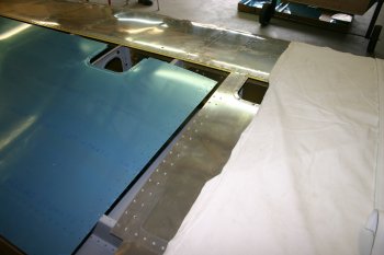 |
| All cleco'd up, I started in the mid wing and worked the cleco's aft and outboard. Needed some jiggling of the ribs in places. | 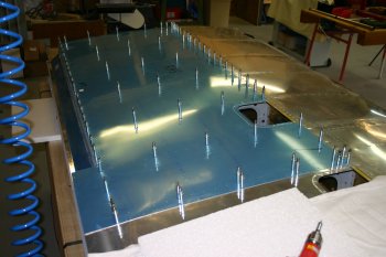 |
| Then the normal #40 drill processing.... I managed to finish the day with the skin uncleco'd and the ribs all deburred (top and bottom). Skin debur and dimple tomorrow after some socialising. | 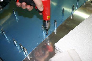 |
Sun 01 February 2004 | |
| First up today was removing the blue plastic protective coating on the RHS lower wing skin along the drilled holes. Then it was then deburred on both sides and the edges smoothed. | 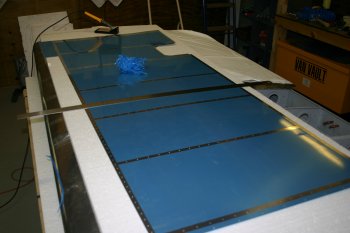 |
| The wing structure was then dimpled. The double thickness areas (end of rib & spare intersections) were dimpled as a single point without any problems. | 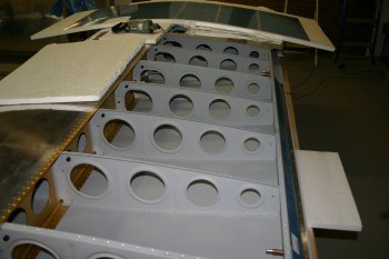 |
| The skin needed a combination of C frame and pneumatic squeezer dimpling . | 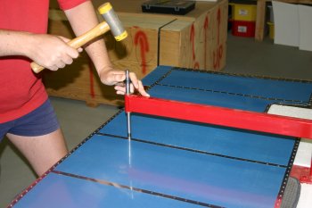 |
| The finished skin, back on the wing for safe storage. | 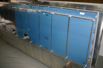 |
Fri 06 February 2004 | |
| Next I moved onto the aileron mounts. This seemed like a good idea at the time. The cleco'ing on of the brackets was easy. | 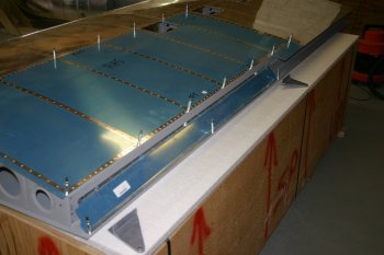 |
| The powder coated brackets that are fixed to the ailerons don't provide enough space to use a socket set / spanner, so we just held the head of the bolt with an adjustable wrench and went from there. At this point we didn't worry about torquing to specific values. | 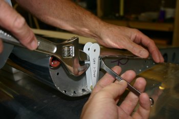 |
| The mounting of the aileron was fairly simple, although the outboard bracket didn't seem to line up very well with the outside edge. | 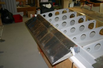 |
| Then I started looking at the clearance of the outboard end bracket. The aft most rivets in the construction manual for the support bracket called out for them to be flush head on the outboard side (which we did and can been seen). The pivot point has a call out of bolt, bracket, 2x -10 washers, support bracket, -10 washer, bracket, washer, nut. The problem is the aileron is then restricted in its up travel with the rivet interfering with the powder coated bracket. One option is to add an extra -10 washer on the inboard side to increase the spacing, but I need to understand if that has other impacts. | 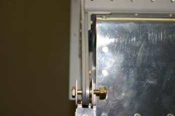 |
| The inboard bracket is a little simpler (or the flush rivet seam to be on the right side) and I made the couple of spacers. I may change one of the -10 to -10L to match the outboard end. Some emails to the lists and maybe one to VANs. | 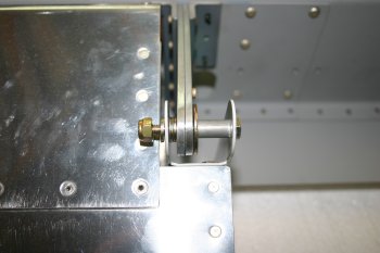 |
Sat 07 February 2004 | |
| I started match drilling the aileron mounts. I first drilled the outboard holes and then the aft ones. I found the aft holes were slightly out of alignment. A long #30 drill bit is needed here. | 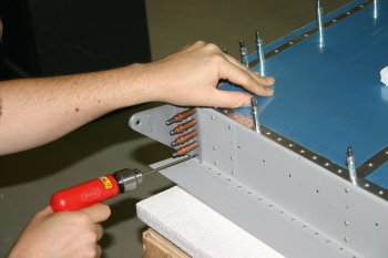 |
| Likewise the middle brackets were match drilled. | 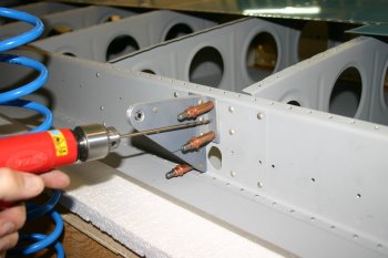 |
| I had missed during the predrilling phase of the aileron brackets that the lowest AD4 rivet was a AN426 (countersunk) so I had to use a long extension in the pillar drill. (Hint - countersink these before you rivet the bracket together!). | 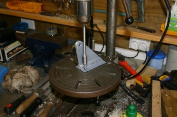 |
| Then onto riveting the aileron brackets to the wing. The Longeron yoke does fit but you have to insert the rivet sets after threading the yoke through the lightening. | 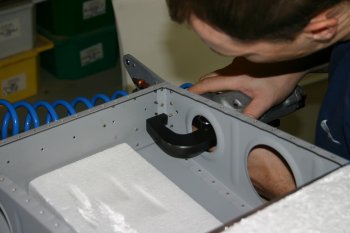 |
| The upper 2 rivets couldn't be squeezed on either bracket due to lack of clearance. Therefore it had to be shot & bucked. This is partially successful, a couple of drill out and reset but all came out OK in the end. Note: Don't use the double offset (the single is better) and having a second person for the bucking makes life a WHOLE lots simpler. (Don't ask me how I know!). | 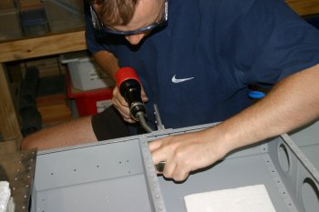 |
| The mounted aileron on the right wing. | 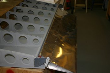 |
| The inner bracket I used a combination of the current plans that I have and the advice from other builders plus the preview plans (which have a different spacer callout). Firstly I over squeezed the aft flush rivets just slightly and I ended up with (from inboard to outboard ie. right to left) - Bolt, mount, spacer, -3, -10, bracket, -10, mount, -10, bolt. This seems nice and snug and moves the aileron one -10 inboard. | 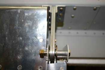 |
| The outboard bracket was slightly different from plans. We ended up with (from inboard to outboard again) Nut, -10, mount, -10L, -10, bracket, -10, -10, mount, bolt. This resulted in good clearance around all the rivets, rock solid pivoting and no deforming of the brackets. The ailerons are well balanced with the counterweighted front nose and really smooth and easy to move. | 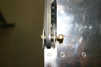 |
Sun 08 February 2004 | |
| With the aileron rigged we could then move onto the flap. With the QB wings (which includes constructed flaps) the only variable we have is where the flap piano hinge goes. | 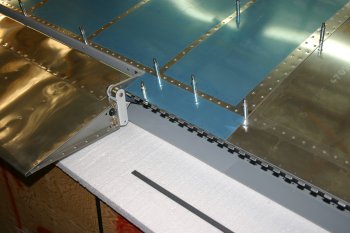 |
| Dad had multiple attempts at getting the first hole aligned correctly (Hint: if you don't cut the hinge to length until after you have drilled it all it is less wasteful of materials!). | 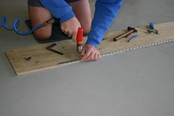 |
| We found the second hole aligned with the edge of a hinge tab worked well and we needed to use the minimum 3/16" edge distance. | 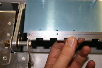 |
| Then it is lots of cleco clamps for try and get the (soft flexible) hinge to stay near the support bracket. | 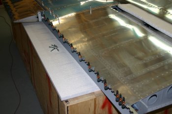 |
| The drill & cleco as we go. | 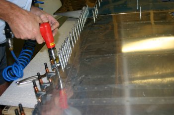 |
| And volia! We are really pleased with the way this has turned out, the gap is 9/32" (which needs to be 1/4" minimum) and the trailing edge is perfect (if that is possible). Now we need to try the same on the other wing. | 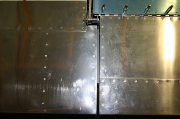 |
| The finished product. | 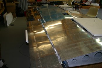 |
| Dad then finished the brace by countersinking for the skin dimples. The third layer of material (the hinge) is left untouched. | 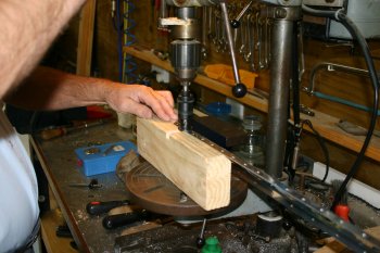 |
Tue 10 February 2004 | |
| And the other wing skin..... | 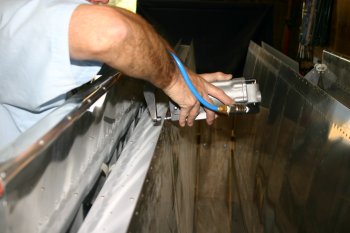 |
| Obviously the right wing needed doing as well for spraying. | 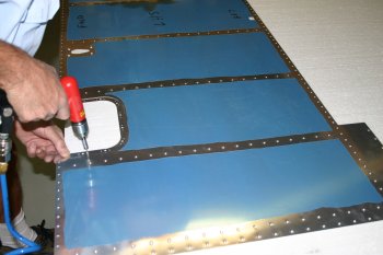 |
Mon 08 March 2004 | |
| I then went onto the aileron bell cranks in the wings. The right hand wing is also is the location we are installing the TruTrak servo. | 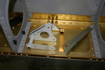 |
| The TruTrak servo connects directly to the bell crank. The drilling is simple enough - 2" from the main pivot point. | 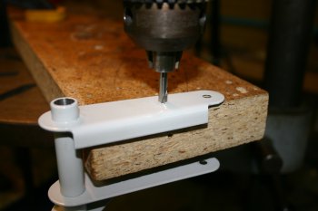 |
| The completed sub assembly. The brass bushing seems extremely tights so that will need more work and I've got an email to the lists asking about the washer lay out. | 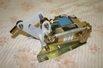 |
| The completed assembly. All looks OK just the brass bushing to be sorted. | 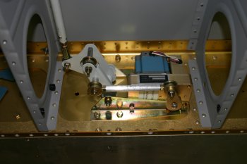 |
Thu 11 March 2004 | |
| First up today I looked at the RHS bell crank. | 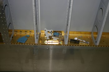 |
| The rubbing was very specific in its location. The bell crank seemed fine (the 3/8 drill dropped through no problems) but the brass bushing didn't rotate fully. I spent time reducing the brass bushing carefully with scotch-brite and the steel crank with a rotating fine grade wet & dry. | 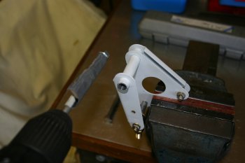 |
| Then I sorted the TruTrak servo mounting. I ended up switching the direction of the lower (as photographed) mounts so the fully threaded bolts go downwards and then a -10L washer with NyLock nut. The orange blobs is the torque seal marker. The upper bell crank pivot is a AN3-13A bolt with two -3 washers. I also primed the AL tubes used for spacers / push rods. | 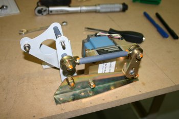 |
| Then it was re-installed and torqued up maybe for the final time, yeah right. For information, additional parts used:
| 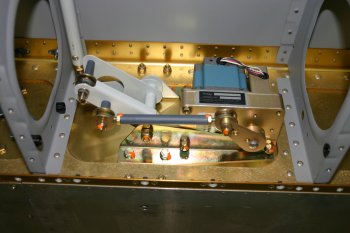 |
Sat 11 December 2004 | |
| For the final couple of hours I did the other wing. As per usual the second time round was significantly faster - about 60% of the original. |  |
Mon 13 December 2004 | |
| Then I finished of the right wing nutplates. | 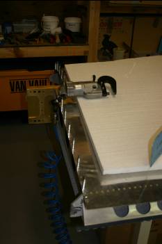 |
| One area that still has to be done is the Angle of Attack system. This requires two ports that sense the upper and lower air pressure on the top / bottom of the wing surface. The issue was that where the recommended location ended up just behind the duck works light location. My concern was it the interrupted airflow might have affected the AOA readings. I sent an email to Jim at AOA systems, and I moved onto something else. | 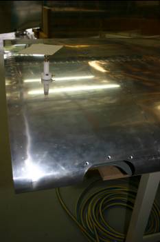 |
| Next up was the tank attach bracket drilling. The blue line shows the 1/2" distance from the edge and the red line is the bracket that was drawn when the wings were attached. | 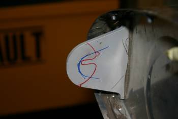 |
| The 1/4" hole is not tricky, just need to get it right! | 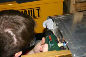 |
| The forward side of bracket then has the nutplate. | 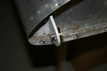 |
| I got a response from Jim to say as long as the locations are 2" ish clear of everything else, it is better to stick with the published position and then the pre-configured parameters should work. | 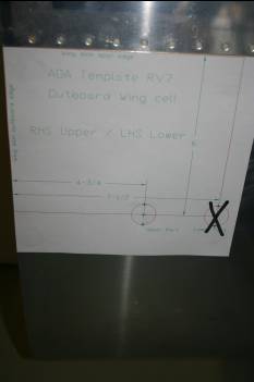 |
| The ports require #4 screws but getting the dimple sorted was a bit of a challenge. I ended up using a AD3 dimpler, and then pulling it down as needed. | 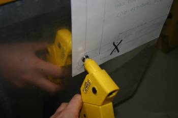 |
Mon 20 December 2004 | |
| I had a quiet day on my own, so I did something a bit different and worked on the AOA drain solution. The upper air port has a drain which has to be accessed from the lower skin of the wing. The plan was to make an additional nylon bushing. | 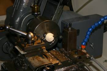 |
| After turning down the nylon I then drilled the offset holes to the same layout as the AOA ports. |  |
| The finished solution, the lower (left side) plug is the new part along with the mid in tube guide. Seems to work OK in theory. | 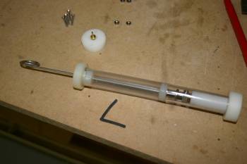 |
| Mounted in the wing. Just about works but I think will need some shaping to try and change the angle the rod enters the wing void at... | 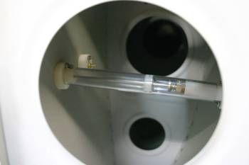 |
Sat 14 January 2006 | |
| Half day with some social time in the afternoon, but first thing got the RHS wing tip in shape. | 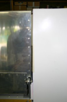 |
Mon 20 February 2006 | |
| I started with the AOA ports on the right wing. |  |
| I still haven't got the #4 screws / nuts so the custom drain affixing will have to wait. |  |
| With the limited working time of the Pro-Seal we just cleco'd the steps on and moved on. |  |
Sun 12 March 2006 | |
| After a bit of a clear up, the RHS wing was extracted from the cradle. We are hoping to get most of the misc things completed on it. I removed the tank cover and starting looking at the fuel sendor and the new VANs Service Bulletin - not a great solution to someones incompotence (IMHO). | 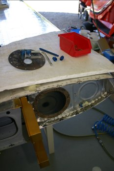 |
| The Duckworks light needs some spacers made which Dad is going to deal with. | 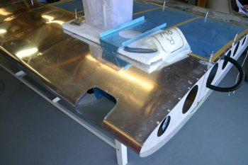 |
| As a finish up for the day I sorted some of the #8 lower nutplate locations. I'll open up the fuselage skin part later. | 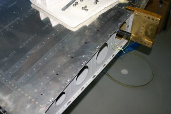 |
Mon 03 April 2006 | |
| Then we cleared the desks and got the RHS wing out. The plane is to try finishing up what we can and then get it re-mounted. I sorted the lower skin nutplates. |  |
| Dad continued with the wing tip lights, working with the template locations. |  |
Tue 04 April 2006 | |
| Then onto the lower outboard wing skin. I feathered and re-edged the skin. This was one of the first parts we worked on, it is interesting to see how the levels of skill have developed. |  |
| One of the challenges with the skin is to get access without putting a crease in it. We used a rope over a roof rafter that worked well. |  |
| Before buttoning up the wing a good vacc'ing and clean up was needed. Also added a couple of draw strings for the AOA and autopilot wiring - should make things easier down the line. |  |
| The lower skin was harder than we expected - we completed the first two bays. The problem ones are the aft outboard of each bay - my arm has the marks to prove it..... |  |
Wed 05 April 2006 | |
| Dad sorted the DuckWorks nutplates and that is another bit ticked off. |  |
| Continuing with the wing skin - things got progressively easier as we moved outboard. The system that worked for us was inboard midway to aft edge, aft edge then forward from the mid point to the spar, outboard to the next rib. Repeat. I did chop and change the method of getting the bucking bar in quite a bit, but none of the options were comfortable or easy. |  |
| The completed skin - the (right) wing is starting to get close to being finished. Major items left - the fuel attach and vent line needs to be sorted, the trailing edge of the wing tips shortened and tip light plexi drilled. |  |
Fri 22 December 2006 | |
| Dad sorted the RHS duckworks mountings | 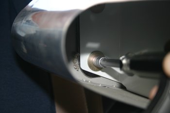 |
| Whilst I did the access panel nutplates. | 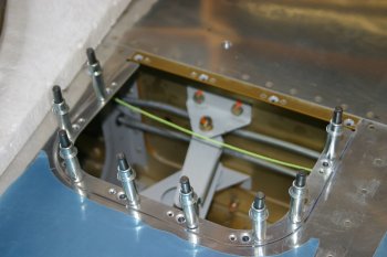 |
Sat 13 January 2007 | |
| Continued with the RHS wing tip modifications, alignment plates now done, trailing edge trimmed. | 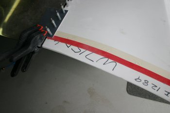 |
| Ready for the glass work, I'll probably wait a while until the weather cools off a little or I have other glass work to do. | 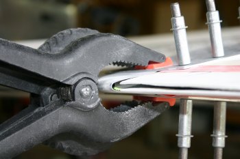 |
Fri 16 February 2007 | |
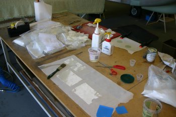 | |
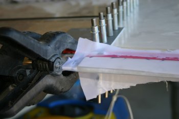 | |
Mon 26 February 2007 | |
| Cleaned up and sanded back the wing tip glass work, also drilled / dimpled the trailing edge rib. | 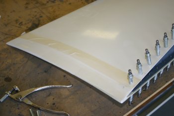 |
| Home | Carl Morgan | Previous|Next|Latest |