


 |
 |
 |
| Home | Research | Delivery | Empennage | Wings | Fuselage | Finish | Engine | Electrical | GRTDecode | Previous|Next|Latest |
| Engine | Firewall Forward | Engine Build 1 | Engine Build 2 | FADEC | Baffles | Plenum | Cowling | |
Plenum | |
Tue 11 October 2005 | |
| I started work proper on the plenum today. First up was finishing the baffles - I ran a 17/64" drill through all the 1/4" screw locations and tidied some of the pro-seal where possible. I also drilled out and re-did a few of the less 'perfect' rivets. The rear fixing of the planned mid section is 12" wide and uses the part #15 mount bolt. | 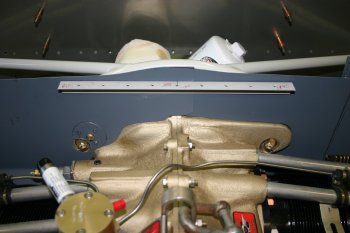 |
| Then I moved to the front section. I want a single support from the centre of the baffles to the side wall - this will provide a number of benefits, including stiffening the whole structure. However the angle needs some 'funky' twists and bends to line up with everything. | 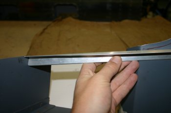 |
| The result of a couple of hours thought and work. Not riveted yet - I'll sort the RHS tomorrow hopefully. | 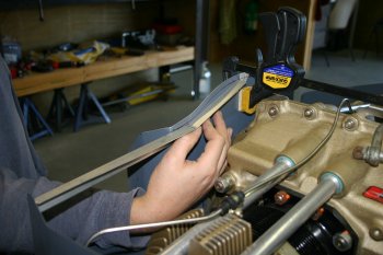 |
Wed 12 October 2005 | |
| I continued with the plenum work. The RHS forward support was first up - same as yesterday - funky twists, angles and trimming. | 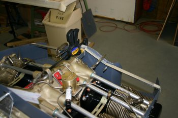 |
| Then sorted the forward brace, slightly tricky as access for the drill is very limited. | 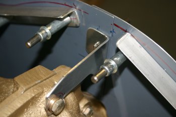 |
| The front braces needed a bit of shaping and I drilled / clecoed them to the front baffles. These will provide the forward support for the centre section. I'm planning on a doubler plate to provide strength towards to front edge. It is a 1" wide strip of 0.20". IF you are going down this route - you don't want holes / clecos here - less is better - I got over keen. | 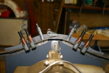 |
| The I sorted the LHS inboard brace. This is another piece of 0.63 angle, with some 'clever' cuts at the ends. A slight twist may be needed but I'll wait until the upper skin surface is sorted. | 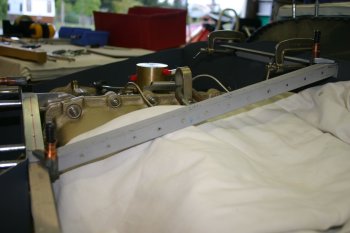 |
Thu 13 October 2005 | |
| I continued with the RHS brace, same process, funky bends and cuts. Not quite as 'right' as the LHS but will work fine. |  |
| Then lots of jigging and measuring to make sure before any holes were drilled. |  |
| Rear brace drilled to the rear baffles. Two additional locations plus the part #15 location. Then jig drilled the 3 parts for the corner locations. |  |
| Finally got to the stage where the fuel divider was annoying me enough to remove it. Carefully done to not bend any of the stainless tubes and plugged / covered the injector solenoids. |  |
| One area that we are considering options was with the rotating of the fuel divider - this will be easier than we first thought as the bracket is pre-drilled with multiple locations. We will also look at the possibility to reduce the height of the divider which may be needed for cowl / plenum clearance. |  |
| With the top surface clear, I made a temporary jig the same width as the aft bracket. The pantograph type contraption can then be adjusted to get the 'best' solution. |  |
| The RHS side (left in the photo) is very good and parallel, the LHS is slightly tapered. Next step is drilling the front locations, currently debating whether to have the doubler plate under / over the braces. |  |
Fri 14 October 2005 | |
| I continued with the frame, more twisting to reduce the need for the parts to be "pulled" into play and trimming of the front baffles to the curved profile. | 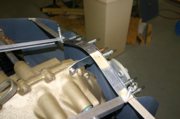 |
| Then I moved onto the top skin for the centre section. I made a rough cardboard template to start with and then went to AL .032" sheet. This may end up being a 'prototype' but we will see how right I can get it first time. | 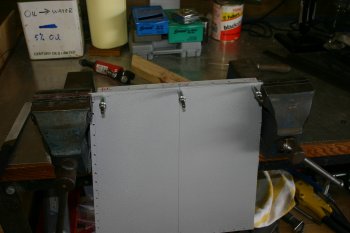 |
| After sorting the rear and front centre locations various options on how / what to do next. The sheet doesn't really want to go into multiple different curves at the moment. | 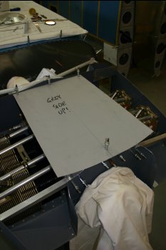 |
| Lots of trimming and shaping of the front edge, fit, mark, trim, repeat...... | 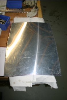 |
Sat 15 October 2005 | |
| I continued on the plenum. The side rails angles were fixed so I completed some of the forward locations. |  |
| This provides a real strong box section. More shaping of the sides and front to allow it to drop in on the front baffle frame. |  |
| Then I put a bend in both the rear edge and the two sides. All a bit of an art form as the bends aren't uniform across the width / length of the skin. Just eye-balled it and did it by hand. |  |
| After various fit / trim / shape / refit this was the result. Suddenly it looks like it might work..... |  |
| I was having problems getting the structure to hold its shape - particularly if I needed to remove it from the engine so I sorted a temporary brace half way down. You can see the amount of deflection needed. The end of the day was match drilling the front section, this will provide nutplate locations for the centre section to front baffles. |  |
Sun 16 October 2005 | |
| I moved onto the side mounting. Starting with the LHS, this is the alignment for the piano hinge. I used a single length with a missing eye at the join of the front / rear baffle. It is also slight further down on the 3/8" cowl clearance. |  |
| After splitting the lower hinge halves and trimming the baffles the top components were started. The top hinge is obviously a single piece and the remaining time available today was spent on the angle section on the rear edge. The basic plan is to have hinge down the outboard edges going into the centre section for nutplate locations. The fore and aft angle will also have nutplates and a Pro-Seal gasket. The whole structure is becoming very ridged and strong. |  |
Mon 17 October 2005 | |
| Today was focused on the outboard lids. Continuing with the LHS, the rear brace was sorted. At this point we removed the mini-baffle as it was distorting the shape. We will probably end up re-making it after the top surfaces are complete and we can see exactly what hole we are aiming to fill. | 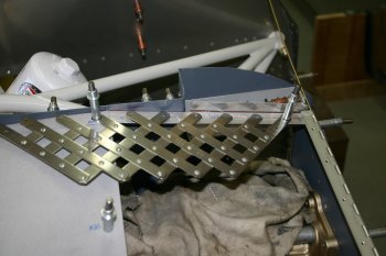 |
| Then it was onto the actual skin surface. After 3 false starts with bad edge distance / trimming I got the rear and inboard shape sorted. Then it was the bending brake again to try and get the basic profile sitting right. | 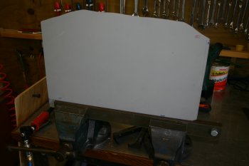 |
| Then with the inboard edge drilled / cleco'd the rear nutplate locations were done. | 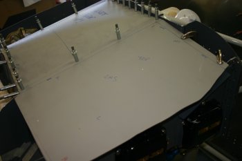 |
| Then trimming of the outboard edge and drilling the upper outer piano hinge. | 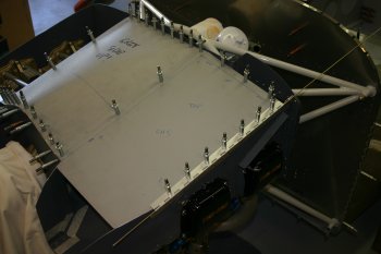 |
| The hinged lid will provide easy access to the engine with the removal of 10 screws. | 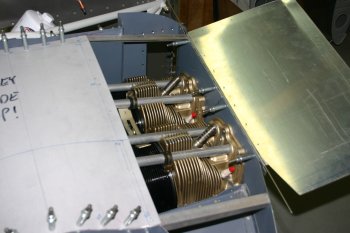 |
| The final part for the LHS is the forward brace angle which provide a link between the side baffle wall and the forward angle brace. A little joggle was needed to get everything to sit right. Also the forward brace tended to move when the skin was cleco'd on - so a temporary tie plate was made whilst drilling the two angles together. | 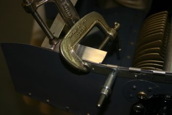 |
| Then it was a repeat process on the RHS. Line up, mark and trim. | 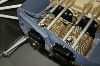 |
| Single length of hinge pin, drilled, clecoed. Marked and cut into halves. Both sides have the join of the front / back baffle parts aligned with a 'gap' on the lower hinge. This means a single upper hinge will fit and hold everything together. | 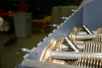 |
| The final step for today was the rear brace on the RHS. Drilled and cleco'd onto the baffle. Tomorrow is the second skin surface. | 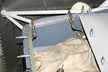 |
Tue 18 October 2005 | |
| Continuing with the RHS top cover, same deal as the other side, shape, trim, drill and form. The bending system of using the home made brake along with two bench vices (one fixed, one movable) worked well. The rear and outboard edges have a set in them, with the corner being the only 'level' square on the sheet. | 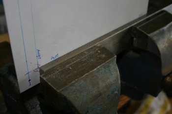 |
| Once the rear and inboard locations were sorted, the outboard edge was trimmed and piano hinge attached. Front edge was then clamped and drilled. | 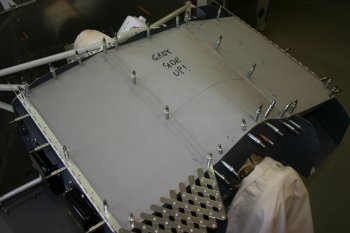 |
| One concern for the RHS is the #1 cylinder upper spark plug - or its lead to be more precise. The clearance is too small so the current plan is to make a hole in the top surface and use a grommet. Might look a little strange with only one lead coming out the top, but functional and simple. | 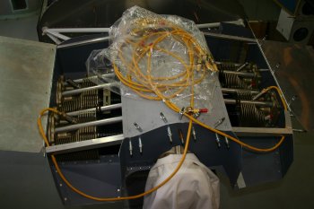 |
| Final piece of strengthening was for the forward corner on the RHS, during which time I managed to drill my left index finger - a rite of passage - but still stupid! This is the whole structure with all #41 holes, the major remaining work is the 'top hat' for the fuel divider and the inlet ducting. Both I'm going to leave until later. | 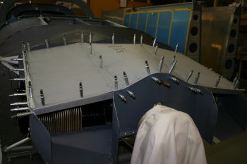 |
| The result of the match drilling, the hinge uses AD3s, the bulk of the rest are AD4s except the nutplate locations. | 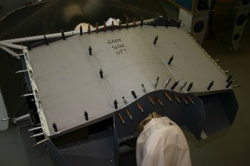 |
| Then I disassembled everything and started the clean up / debur process. I was going to get keen and do the nutplates - but I realised my match drilling used #21 rather than #19 as needed. At this point I called it a day and will sort tomorrow. Overall good progress, plenum is basically made although quite a bit of 'finishing' to complete yet. | 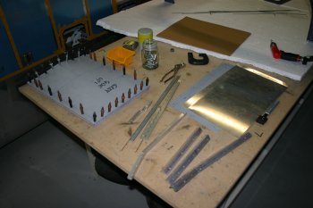 |
Wed 19 October 2005 | |
| Finally it was back to the plenum, opened up the rear locations to AN3 bolts. | 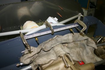 |
| The rest of the day was countersinking, dimpling, de-burring etc the various plenum parts. | 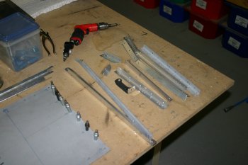 |
Fri 21 October 2005 | |
| More deburring / plenum finishing, starting with the countersinking of the hinge for skin dimples this morning. I'm trying to continue with flush (AN426) rivets on the inner surface of the plenum where possible. | 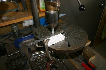 |
| Then I moved onto one of the problems left with the plenum. The fuel divider is too high for the top center surface. I'm guessing there is only about 3/8" maximum to the cowl so getting another surface between them is going to be challenging. | 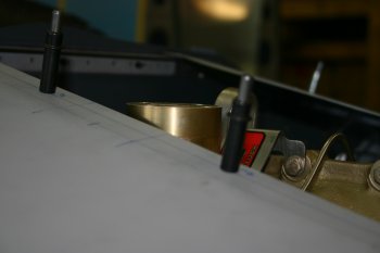 |
| First up I slotted the mounting bracket for the divider - this gains us about 3/16" which is a good start. | 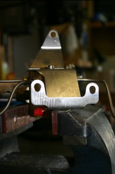 |
| Then I marked and drilled a small location where the interference was. |  |
| This was then progressively enlarged with a half round to get a mini-cut out. | 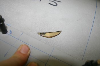 |
| Meanwhile, after looking at the mini-baffle over the oil cooler we dicded it was going to need too much 'filler' on a couple of corners so Dad made the 3rd bracket...... | 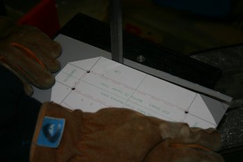 |
| This one fitted nice and tight and the remaining rear brace was drilled to it. | 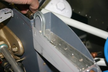 |
Sat 22 October 2005 | |
| Not much done today - a few bits of countersinking and deburring and begining of prep for spraying. | 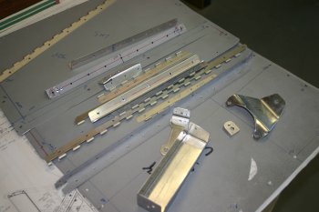 |
Sun 23 October 2005 | |
| Today looked much better for spraying so we started early and scuffed and AllSol cleaned any parts we could find that needed processing, mainly plenum but a few hinges and other bits. | 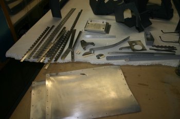 |
| Then normal system - De-oxidine and wash. | 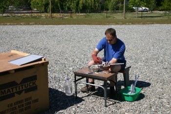 |
| Whilst drying in the sun I'm now also using compressed air to try and drive out any sitting water, particually on piano hinge. | 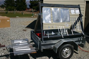 |
| The total of todays effort, other domestic things this afternoon. | 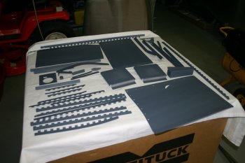 |
Wed 26 October 2005 | |
| I squeezed a few nutplate locations and misc bits. | 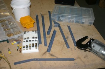 |
| Then it was back to black goo (Pro-Seal) for the plenum structure. Lots of masking / prep. | 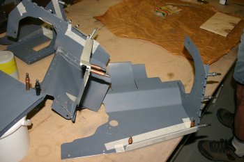 |
| We are getting better with Pro-Seal generally, I now use masking tape to protect / get a clean edge of the black stuff. Dad did the application again and I did the squeezing. |  |
| Resultant pile of new bits. The top centre section we are doing in two sessions, otherwise the plenum is pretty much done. I let the Pro-Seal set for a couple of hours and then cleaned the masking tape up before it hardened. | 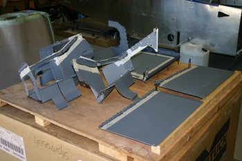 |
Thu 27 October 2005 | |
| I started by reattaching all the baffle and plenum parts to the engine. This enabled a check of the cowl clearance and also lets everything 'set' in the right shape. | 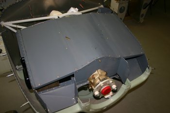 |
Tue 17 January 2006 | |
| I also played with the a possible forma for a 4" round cylinder - this might work well for any new inlets we might need. | 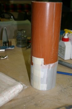 |
Wed 18 January 2006 | |
| With the temperatures well down (16C ish) I did some experimenting with fibreglass. One of the remaining challenges is the transition between the cowl and the plenum - particually on the upper surface. One idea is for a new inlet structure, so I tried making a 4" cylinder from 3 layers of 6oz BID. Layup went pretty well, the net result wasn't that great - see below. | 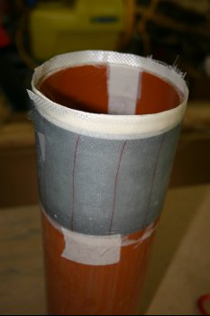 |
| I spent the last hour or so, trying to extract the forma from the fibreglass test. I ended up running a piece of .032" material between the surfaces and then splitting the pipe from inside. Finally managed to extract the forma. The peel-ply didn't work that well, the outer layer had become saturated, this meant it was impossible to remove. I used a couple of plugs to re-expand the forma and left to cure abit more.... | 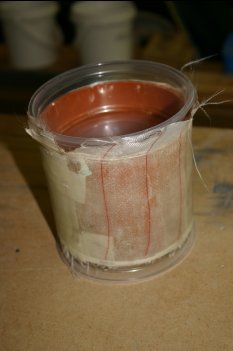 |
Sun 29 January 2006 | |
| One of the bigger problems remaining for the custom plenum is the transition between the cowl and plenum. This was a first attempt at making a forma. This didn't work well, the clay dried too quickly and cracked. More thought needed.... | 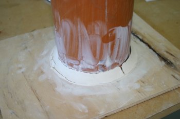 |
| The 'other end' of the transition needs to go into the plenum - this wooden template is the first step. | 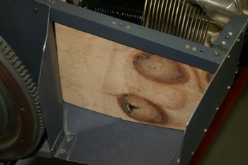 |
Mon 30 January 2006 | |
| Back to cowl / plenum connection - the new plan is to use two 2" long AL 4" tubes in each of the lower cowls and then join those to fibreglass transitions attached to the plenum / engine via baffle material or something similar. | 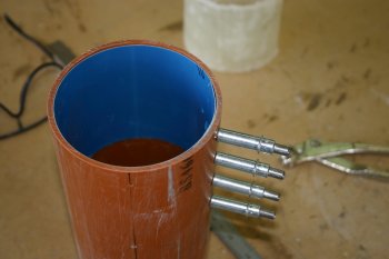 |
| More experimentation (as we don't really know what we are doing!), this time with a clay forma on the wooden exit template that I made yesterday. | 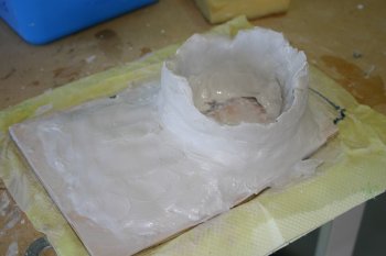 |
| The finished forma after more smoothing - left to dry a bit over night. | 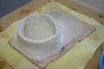 |
Tue 31 January 2006 | |
| With the left over micro I painted the clay mold and then laid up some 2oz / 6oz cloth. Only about 4 layers but should get the basic shape / prove the principle. | 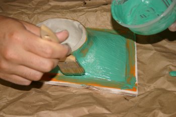 |
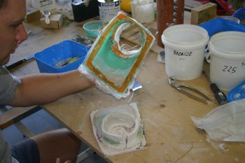
| The glass experiment was also set so I extracted it from the clay forma. | 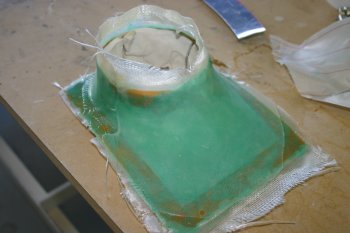 |
 | |
| After some trimming an initial fit looks encouraging, only concept at this point but a step in the right direction. I think probably the cowl side needs to be sorted first, then probably a wooden forma for the glass. I also ordered some more composite materials today - getting low.... | 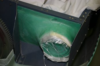 |
Sat 18 March 2006 | |
| First thing dealing with Stein in the USA, hopefully my avionics should be picked up today, but I won't hold my breath. Back on the project a bits day, the forward outboard corners of the plenum need to be trimmed to clear the new cowl inlets. Tin snips for the .032 and sabre saw for the AL angle corners. | 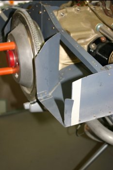 |
Thu 30 March 2006 | |
| I finished with more thought and preparation for the cowl / plenum mating. It will need to be a fibre glass structure, getting foam for a mold is proving difficult so I may go back to clay. An AL sheet as a backing plate was cut. |  |
Fri 12 May 2006 | |
| Then with the temperatures doing well today I took a break for some proto-typing. Using expanding building foam I'm trying to make the basis for a plaster plug for the cowl inlet / plenum diffuser. | 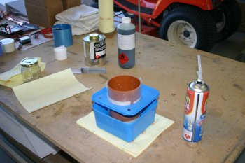 |
| The foam keeps expanding for quite a while. Tomorrow's question will be does the PVA release agent allow the the tube to be removed from the foam - we will see..... | 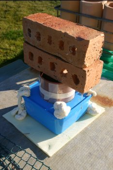 |
Sat 13 May 2006 | |
| First up the experiment - fairly sucessful, I'm not sure if this will be the method we use, but in principle it works - the release agent seems a little difficult to get rid of. | 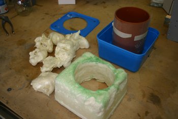 |
Sun 14 May 2006 | |
| Going back to the inlets today, decided to focus on just the RHS to start with - slightly more space to work with. I cut the baffle floor further back and bent it downwards, | 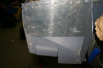 |
| I used a length of 4" pipe which hopefully form the aft ring for the joint. Then strips of .025 AL were drilled and cleco'd to hold the ring in place. | 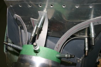 |
| I extracted the parts and re-assembled on the bench. I used some screws to replace the clecos and a backing board to keep in planar. |  |
| Then mixed some plaster of paris and started building up the layers. | 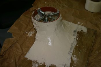 |
| After the first session had cured a bit, the lower profile was built up. I think it is probably going to be a two piece shape. Tomorrow I'll try shaping it further. I have no idea if this is going to work for a fibreglass plug - time will tell. | 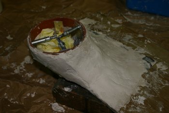 |
Tue 16 May 2006 | |
| Once the plaster-of-paris (PoP) had set off a bit, it was obvious that the two different batches didn't key together very well. Lesson learned - do it in a single batch. After some attempts at recovery, I decided better to start again, so I sawed the mould away and restarted from scratch. | 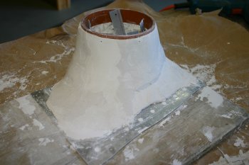 |
| This time I protected the 'inner core' with some masking tape and marked the edges with blue electrical tape. | 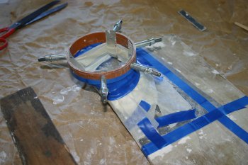 |
| Then a big batch of PoP to get the basic shape. | 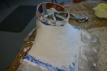 |
| Lots of scraping and a bit of rasp file work got the surfaces in roughly the right layout. | 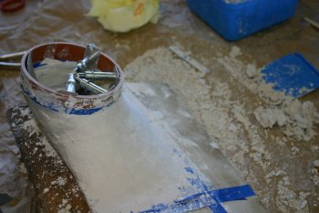 |
| The finish wasn't particularly smooth, so I decided to use clay as a finishing surface - this has the advantage of being workable over a longer period and the PoP seems to help keep the moisture in the clay. | 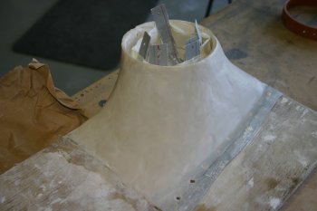 |
| Then to provide a release boundary I used cling film and prep'd for the fibreglass work. The glass layup went well - using reasonably small triangles of fabric I covered the upper half of the mould. | 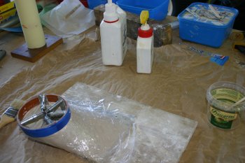 |
| As a single piece can't be removed from the plug, I used two lines of electrical tape and continued with the lower half of the mould. Only a few layers of 2oz cloth - I just want to get the shape / prove the principle, then I can bulk it up. | 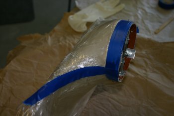 |
Wed 17 May 2006 | |
| Had a bit of difficulty extracting the forward edge of the fibreglass and it was still a little green. | 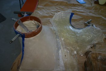 |
| The second problem is the clingfilm is never completely flat and it has resulted it voids on the inner surface of the fibreglass - more so than I really want. | 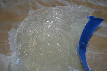 |
| Therefore it was back to fibreglassing, this time I used release agent directly on the PoP / clay plug. Also the resin mix was more consistent, I only worried about the upper half at this point. | 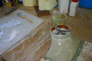 |
| Curing is becoming more of a problem with the air temperatures dropping and winter coming - I did get a bit of sunshine on it however. | 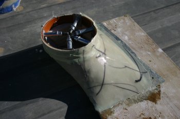 |
| With the RHS all curing, I moved to the LHS. This is a little tighter in space, but same deal. I started by trimming the lower baffle floor, bending it back, I ended up just trimming it off. I think I'm going to need to do some serious trimming on both the forward baffles, but I'm trying to put it off as long as possible in case I need the material. | 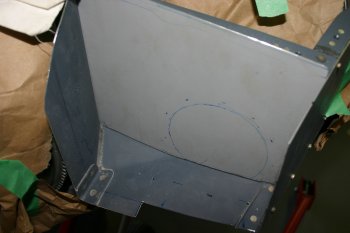 |
| As always - the second one is faster and easier. This time I just focused on 3 attach points to get the ring in the right plane and right location. | 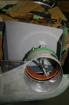 |
| Then PoP and clay for the finishing layer plus release agent. | 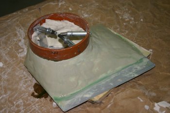 |
| Fibreglassing upper section again, multiple smaller pieces of cloth, left to cure overnight. Not sure if I'll be able to work with the fibreglass tomorrow or if I'll have to wait a day, might have to find something else to focus on..... | 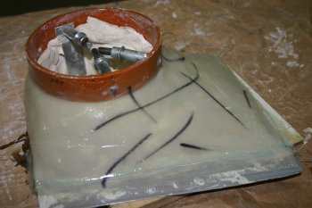 |
Fri 19 May 2006 | |
| Continuing with the plenum diffusers, took a careful extraction process from the molds. The PoP seems to have stayed in one piece, the clay has remained on the fibreglass. The RHS was the earlier mould and it looks like it is too high at the top. |  |
| On positive side, it seems to have a nice curve and should work in prinicple. |  |
| The LHS is much better, the top half of the diffuser seems to match up well and now the attachment problems start. |  |
| The lower edge also need more thought - I think the significant trimming of the baffle floor is going to be needed before hand. |  |
Mon 12 June 2006 | |
| Then back to the plenum inlets - I decided the LHS was the prefered starting point, there is slightly more room and a things are just a little easier to work. First up major trimming of the baffles - mixture of snips, sabre saw and finger file. | 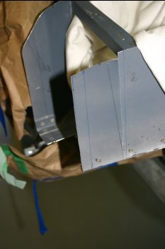 |
| As a slightly different track on the mounting of the diffusers, I've decided to make a AL 'ring' as the backing plate for the fibreglass work and then screw / rivet that to the plenum. Not sure if a good / bad idea yet, but an approach! Added a couple of #40 clecos on the top bar. | 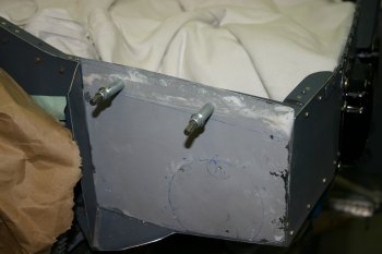 |
| And then lots of templating, cutting, trimming and shaping. The basic form was done on card, then CAD conversion. Seems to work quite well, the wrap around on the bottom should be simple to drill, the 'tongue' on the inboard edge provivde vertical 'stiffness'. | 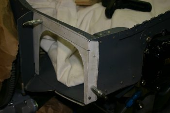 |
Tue 13 June 2006 | |
| I continued with the diffuser - more fixing locations for the AL ring. | 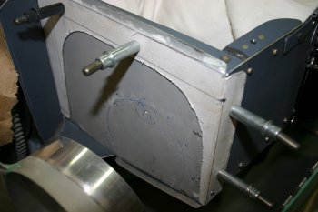 |
| Then the spacer to hold the 4" ring in the right location. | 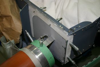 |
| Plaster of paris for the bulk shaping, difficult to make it stick 'vertically' but enough once it all starts to set. The plan this time is to make a rough postive and then pour a PoP negative mould (probably in two halves). This will then be used for the glass layup - pros - hopefully will provide the right solution for attachment, cons - the mould will be for the outer surface (which doesn't have air going past it). | 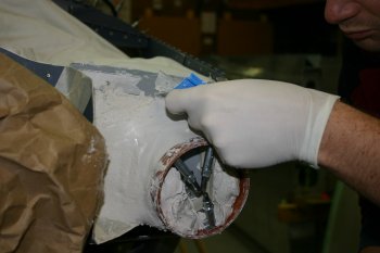 |
| Then removed the backer and mould, made a wooden locating support and prep'd for clay. Tomorrow it is clay + release wax, then PoP and see what the result is like...... | 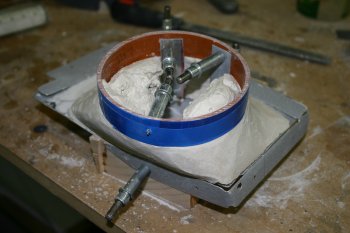 |
Wed 14 June 2006 | |
| I was still on the plenum diffusers. A small amount of clay to finish the outer edges and then release wax which went on well for a finished surface. | 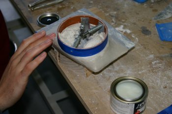 |
| Then using PoP again, a negative mould was mixed. | 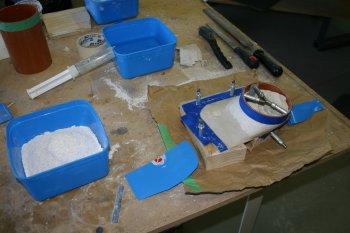 |
| I was quite generous with the edge build up and also added two dividers to split the mould. | 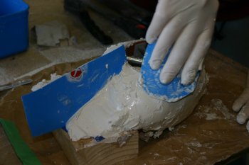 |
| Getting the mould to release was tricky (and not bending the metal ring), I just took it slowly and work everything through. | 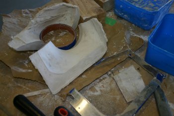 |
| The result is pretty good, not completely smooth but fine for the exterior of the diffuser. | 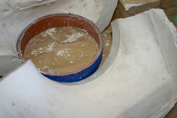 |
| Once everything had dried off a little, the negative mould was drilled for the cleco locations and the AL ring protected with electric tape (to help the release process). | 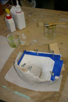 |
| Then multiple triangles of 6oz glass + resin was added, plus some strips for the round forward edge. | 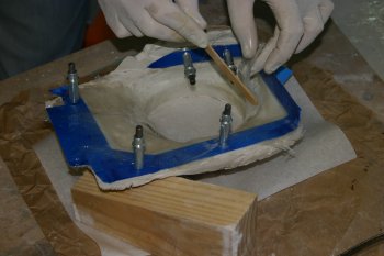 |
| The edges were held down with cleco and the layout left to start curing. | 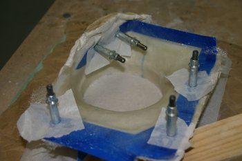 |
Thu 15 June 2006 | |
| I did manage to extract the inlet duct from the POP mould, but it required breaking the mould which was disappointing. | 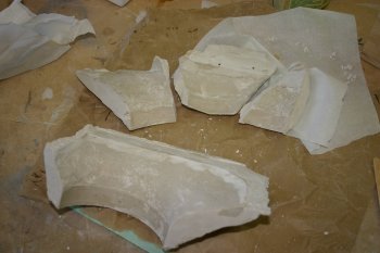 |
| Then I cleco'd it to the plenum, this should help it cure in the right shape. | 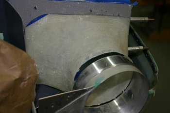 |
| Looks promising, just the outboard edge of the forward ring that isn't quite aligned - about 1/8" too far inboard - probably good enough however for the rubber transition. | 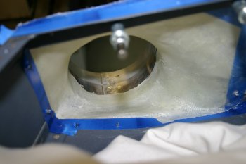 |
Fri 16 June 2006 | |
| After removing the AL ring and the electric tape, I setup the bench as a reference surface. All the AL was really scuffed and cleaned and the previous days glass lightly sanded with 80 grit to help the keying. It is still a bit green so it should chemically bond also. | 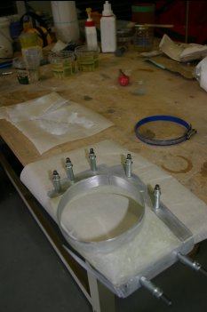 |
| Then more glass work, a single layer of 6oz under the upper and inboard edges, then a metal hoop in the front edge and layers of 6oz glass to hold everything together. | 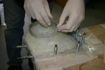 |
| Once one or two layers over the AL components I moved the whole structure onto the plenum - this should help cure / set eveything in the right shape. | 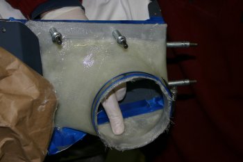 |
| To help set the front ring I used the ring clamp to get a circular shape on the outside and had the 'bright idea' to use a balloon to expand on the inside. | 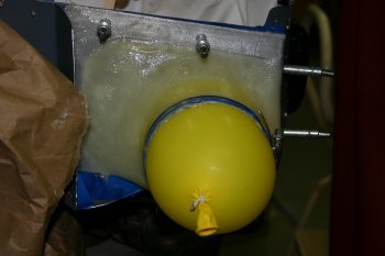 |
Sat 17 June 2006 | |
| The balloon worked well and the shape looks good, a couple of small lips to worry about but the basic structure is good and strong. | 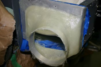 |
| The problem was I couldn't get it off the plenum - the electrical tape wasn't providing a good release and the 'green' resin was sticking very well. After more thought and taking some time / patience with a putty knife I did manage to extract it and remove all the tape. I decided not to add any additional glass today and let it cure further - I'll add a final layup tomorrow and then worry about microballoons on the inner surface for smoothing. | 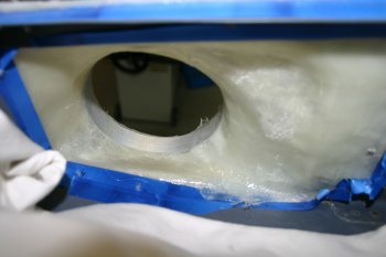 |
| One down, one to go. Onto the RHS inlet, extracted the AL from the old PoP mould and drilled the upper and outboard locations. | 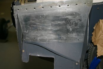 |
| Spent the rest of the afternoon making a new AL ring, some interesting bends and folds for the lower corner and normal templating / forming process for the front. Goes quicker second time around as I have some idea what I'm aiming at! | 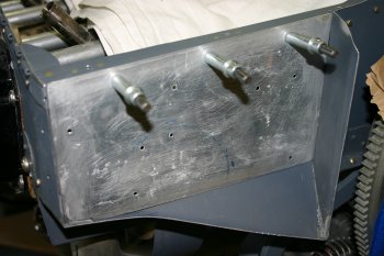 |
Sun 18 June 2006 | |
| Continued work on the AL ring (2 parts) for the RHS inlet. The edges were then trimmed and mini brackets added to locate the vertical plane. | 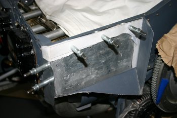 |
| LHS inlet, more sanding, trimming and prep, then additional layers of 6 oz cloth on both internal and external surfaces. Generally tried to use larger pieces on the inner surface to get a smoother overall profile. | 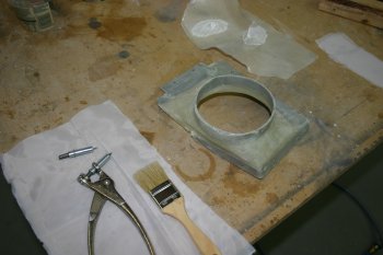 |
| I used peel ply on the aft surface (which partially worked) and a final 2oz strip on the outer round profile. All let to cure over night. | 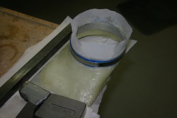 |
Tue 20 June 2006 | |
| Continuing with the inlet diffuser, I've decided it is strong enough and it is smoothing and finishing needed. Micro-balloons, mainly on the inner surface, plus some straight resin in a few areas that were lacking. | 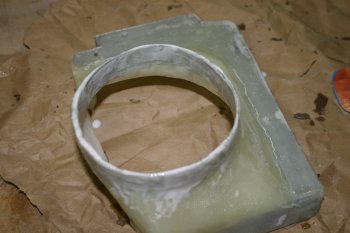 |
| Then whilst things were curing (slowly due to the cold) I returned to RHS inlet. With the lower cowl re-mounted, using the long version of the 4" tube, I remade the support brackets (multiple times). | 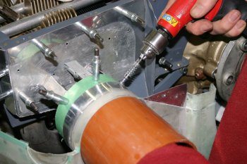 |
| Final solution ready for plaster of paris. | 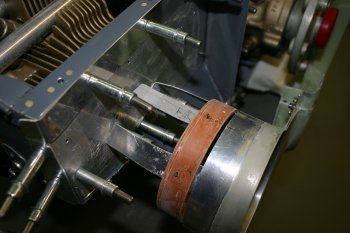 |
Wed 21 June 2006 | |
| Remounted all the supports for the front ring inside a plastic bag - hopefully this will protect the clecos and help with the sticking of plaster of paris vertically to the under surface. | 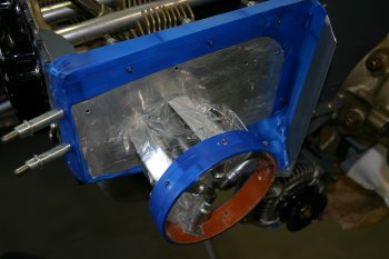 |
| Add a couple of measures of PoP and rough shaping with a squeegy.... | 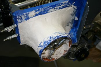 |
| Forming it on the actual plenum does help get the 'proportions' right, but I cleaned and masked up as much as possible, also some release wax on top of the electrical tape. | 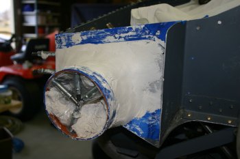 |
| One potenial problem is the lower shape, probably too much like that and will need 'trimming'. Short day with social lunch / afternoon. | 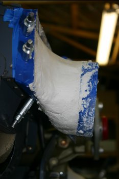 |
Thu 22 June 2006 | |
| It did require significant shaping - a mixture of vixen file and also general purpose wood saw. | 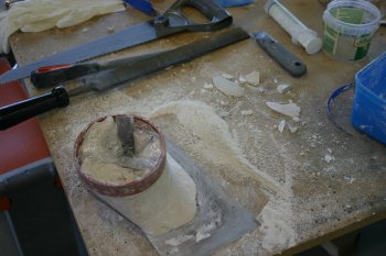 |
| Then it was the potery clay to finish the profile and fill-in the gaps. The forward ring has a strip of AL which will hopefully result in a better circular ring than the LHS. The various bits of AL were covered with electrical tape. | 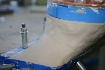 |
| The release wax was put on fairly thick and left to cure, hopefully the negative mould should release with greater ease. | 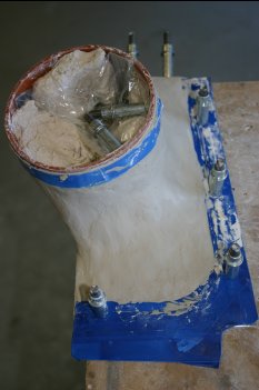 |
| The actual PoP negative was easy to layup, a couple of dividers to enable the extraction of the halves. | 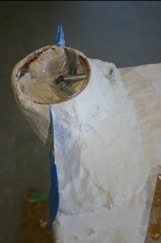 |
| Much easier this time to split, I left the it all to dry of over night. | 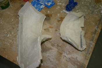 |
| To finish the day a couple of hours on sanding and shaping the LHS inlet and the getting it all to fit again. Nearly there, even the experience on the LHS has meant the RHS will be better - again the 'second one' as is normally the case. | 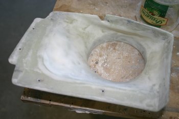 |
Fri 23 June 2006 | |
| The forward ring provides a good way of holding the two halves together, I'm glassing in the AL parts on the first pass, rather than extracting and floxing in later. More wax release on the PoP mould. | 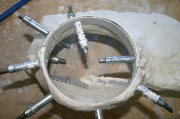 |
| Then normal clear the decks and prep for resin work. | 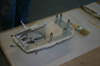 |
| I used multiple triangles of 6oz, first from the ring and | 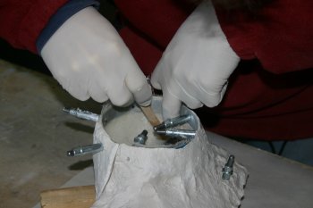 |
| then from the back surface. I used a balloon to keep the inner surface smooth - tomorrow hopefully I can extract and continue the buildup. | 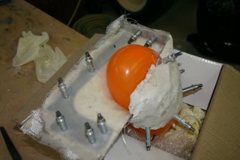 |
Sat 24 June 2006 | |
| Well the day started well, I brought the RHS inlet into the warm / sun to start speeding the curing process - however without the front clecos holding the ring, the PoP slipped slowly down. |  |
| This resulted in a deformed shape and a complete mess. I tried to recover the situation by moving it onto the plenum, but it was a lost cause - back to square one..... |  |
| The 'good' news was that I didn't have to break the negative mould, so I extracted the AL rings from the old failed one and cleaned / sanded everything back. Then it was back to the fibreglassing, mixed more resin this time, laid up some 'halves' on the PoP mould and then joined the sides together. |  |
| Also added another couple of cleco locations to hold things down / in the right place. |  |
| Then the balloon trick again to keep it all pressed up against the mould and leave in the warm over night. |  |
Mon 26 June 2006 | |
| RHS inlet - destroyed the negative mould and extracted the fibreglass. Then went to town with the finger file and knife | 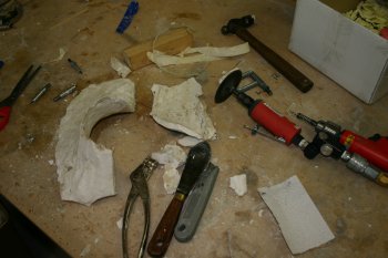 |
| Got it to fit roughly - the upper outboard corner is still a bit of a problem, but otherwise looks promising. | 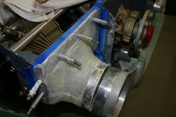 |
| More sanding / excess resin removal. One outstanding issue is the alignment between the cowl and inlet ring - I don't think it will be a big problem, probably just sand more from the outboard edge. | 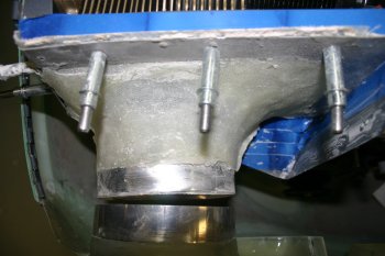 |
| A small amount of glass work was done, this is mainly to hold the outside of the forward ring, plus redo the corners and inboard join where the sanding had removed 'generous' amounts. | 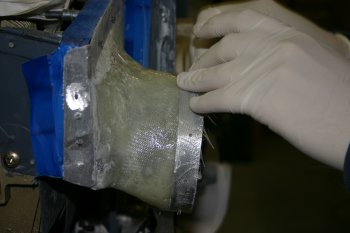 |
| Finishing point for today in the shed. | 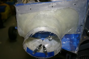 |
Wed 22 November 2006 | |
| I spent the rest of the day looking at the cowl inlet / plenum inlet configurations. Even though it is about generation 4 & 5 I'm coming to the conclusion they aren't going to work so I need a new plan.... I don't mind re-doing things when they aren't right, my problem is finding a new method that I think might work - no point re-doing what didn't previously work! | 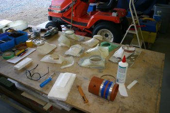 |
| Very frustrating and a bit depressing - the builders out there will understand, we all have days where the problems just seem a bit big - we will get there, but motiviation is pretty low and worries fairly high. One part that I know I need if I'm going to remake the plenum inlets are the 4 3/8" AL rings - so to do 'something' I made two of them. | 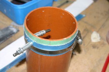 |
Thu 23 November 2006 | |
| I remade a backing plate for the LHS plenum inlet - only 025 AL but should provide some structure to build up on. | 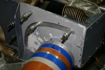 |
| The problem is it is just too small a space to get a smooth transition between the round inlet, through a flexible connection to a ring connection to the main plenum volume. I think more trimming of baffles is going to be needed - but sleep on it first. | 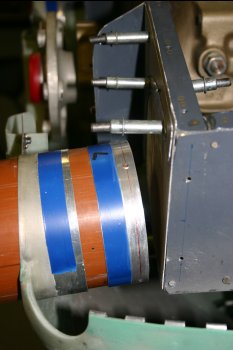 |
Fri 24 November 2006 | |
| New day - talked it over, and decided to trim more! | 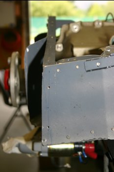 |
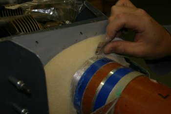
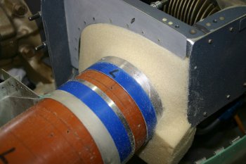
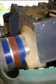
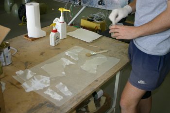
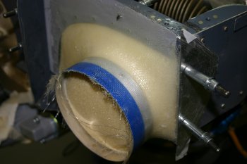
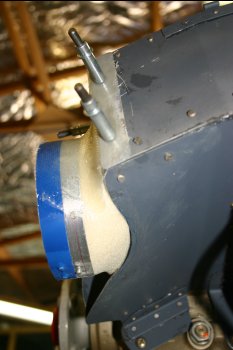
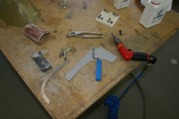
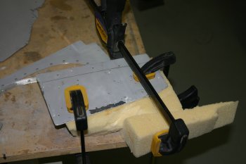
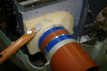
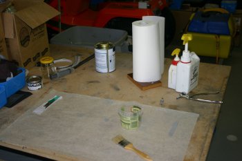
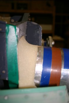
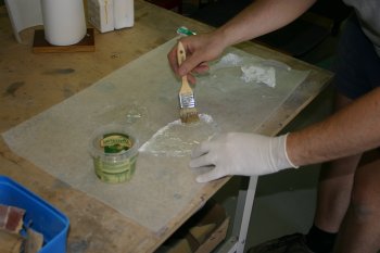
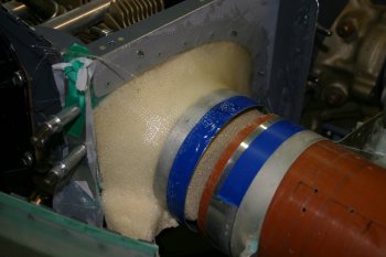
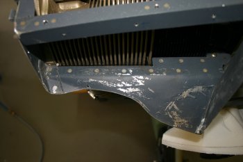
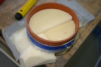
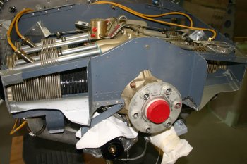
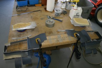
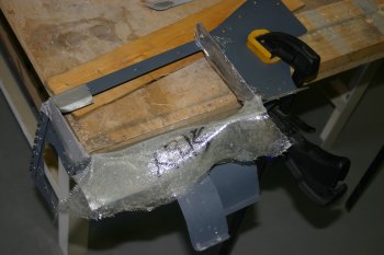
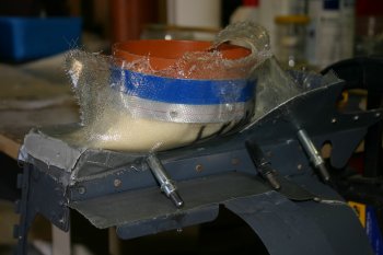
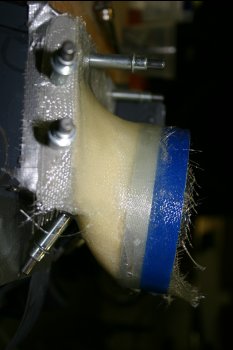
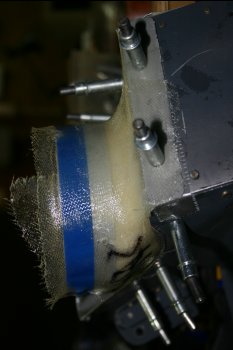
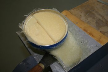
| Then onto new techniques - I managed to get some foam from a fibreglass specialist in Queenstown yesterday. He generally advises against foam, and prefers clay, but when I need to have something shaping against gravity I think this might work better. Also in NZ it is very hard to find XPS (extruded polysterene foam) - it is locally known as 'gold foam' and used in some comercial buildings, but I can't find any sources for local off cuts. | 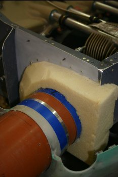 |
 | |
 | |
 | |
 | |
 | |
Sat 25 November 2006 | |
 | |
 | |
 | |
 | |
 | |
 | |
 | |
 | |
Sun 26 November 2006 | |
 | |
 | |
 | |
 | |
 | |
 | |
 | |
 | |
Mon 27 November 2006 | |
 | |
Tue 28 November 2006 | |
 | |
Wed 29 November 2006 | |
 | |
Thu 30 November 2006 | |
| Then back to prep, setup and more glass work on the plenum inlets. | 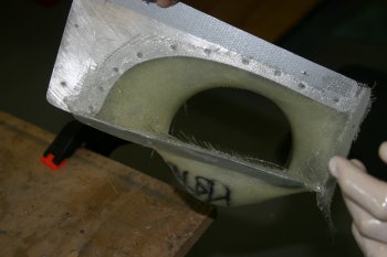 |
| On the LHS inlet I added some 6oz cloth on the inner surfaces and then repositioned on the plenum. For the RHS I did both inner and outer surfaces. | 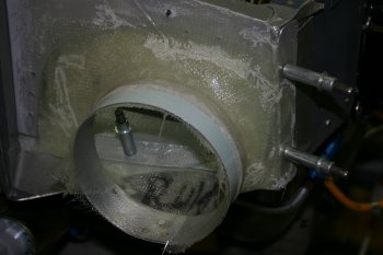 |
Fri 01 December 2006 | |
| More fibreglass work today, the new delivery included some 6oz and 9oz cloth. I used the heavier 9oz on the oil cooler exit duct. Not sure if this is going to be a waste of time, but easier to do it now whilst we are in the mood / mode. | 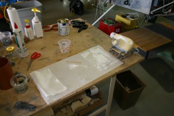 |
| Also added another layer on the outside of the LHS plenum inlet. Both sides will need another 2oz finishing layer on the inner surface, but I want to try and finalise the shape / fit and strength before getting there. | 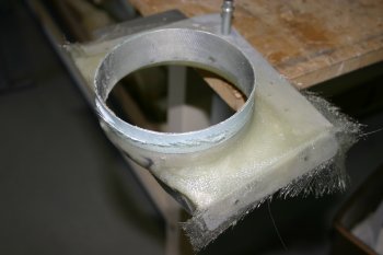 |
Wed 06 December 2006 | |
| A small amount of sanding and clean up work completed. | 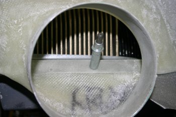 |
Thu 07 December 2006 | |
| Then 2oz finishing layers on the lower surfaces of the plenum inlet - left | 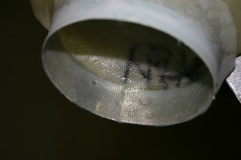 |
| and right. This side was more problamatic to get a neat solution. | 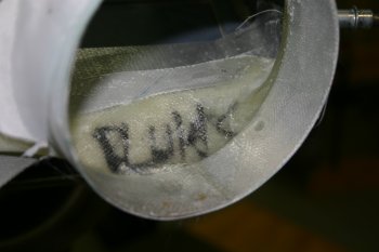 |
Sun 10 December 2006 | |
| Not many photos - but a good productive day of glass work. 4 'pumps' completed, multiple layers on the inner surfaces of the plenum inlets and oil cooler duct. | 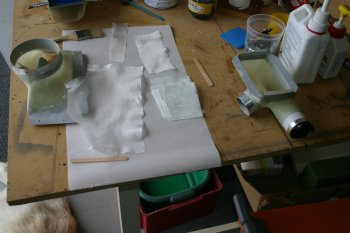 |
| I used the balloon method again to get the inner surfaces to bond / saturate fully - works although a small ridge of resin is left at the edges that will need to be sanded out - no big deal. | 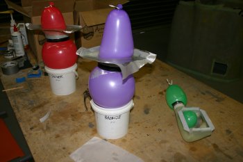 |
Mon 11 December 2006 | |
| I continued with the glass work, cleaning up yesterday's session and starting the sanding / smoothing. | 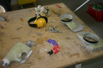 |
Thu 15 February 2007 | |
| With excess pro-seal mixed, I grabbed the plenum cover and tried to sort the forward edge. The idea is to let this set (as a glue) and then dimple / rivet / fill as needed. | 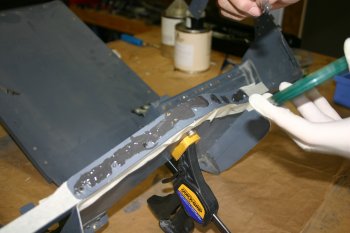 |
Sat 17 February 2007 | |
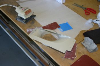 | |
Mon 26 February 2007 | |
| Short bits day - squeezed the remoaing rivets on the plenum upper cover - only remaining work on that is the 'fibreglass bubbles' for the fuel spider and possibly #1 upper plug/lead. |  |
Wed 28 February 2007 | |
| I finished the baffle lower tabs and trimmed yet more from the front. | 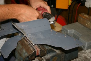 |
| The 4 corner baffles parts nearly ready for final painting. Painting is very optional, but I've decided the ability of easy cleaning and visual inspection makes it marginally worthwhile. | 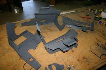 |
Thu 01 March 2007 | |
| One of the challenges with the yellow high temp paint is the longer drying time - this removes the option for using the 'bird frame' for painting - the new solution is a suspended bar with concrete blocks teathering the ends. Wire hooks for hanging the parts. | 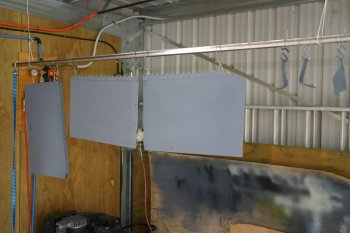 |
| The bottom edge was held by hand and then by a wire line whilst the spraying was completed. | 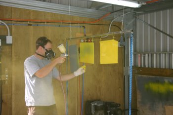 |
| Also did the upper plenum components and another black coat on the panel. The panel paint ran out a little too quickly - I'll review tomorrow. | 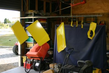 |
Mon 12 March 2007 | |
 | |
 | |
Fri 23 March 2007 | |
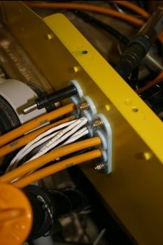
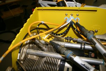
| Reinstalled the rest of the plenum and continued playing with the push/pull cables. The throttle bracket looks like it is going to be a problem - the P2 cable seems to be lacking in downward angle - hopefully it won't mean a complete re-fabrication of a new bracket | 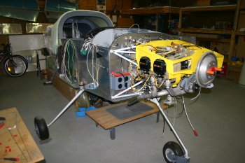 |
Sat 24 March 2007 | |
| Then some trimming / adjustment of the plenum center section to go around the fuel pressure sensor. | 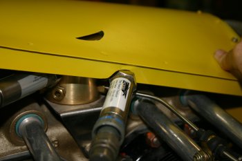 |
Sun 25 March 2007 | |
| Also fixed / finished some of the hinge pin retention for the plenum. On this occasion I'm going with a simple safety wire solution. | 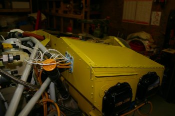 |
Mon 26 March 2007 | |
| I had two known area on the plenum which were a problem. The first is the fuel spider in the middle panel - I've already cut a simple smiley for it, the second was still to be decided. The number 1 cylinder top spark plug has a conflict with the upper plenum cover. The options considered were; simple grommet and spark plug lead through the surface or another 'bubble' to allow it to stay below the surface. I chose the second option so back to cutting holes with the rotorary burr and finger files. | 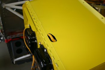 |
| Then plastic / tape to protect the paint work and clay moulds to provide the cover shapes. This was then finished with some release wax and left to dry before glassing. | 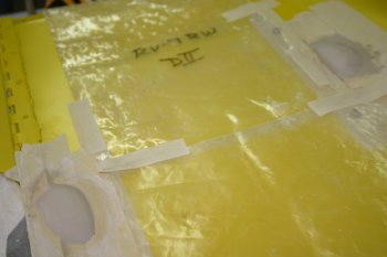 |
| Then onto glass work again - nice temp to be working in (~23C) - things don't go off too quickly, but will harden overnight. The bubbles were simple enough - the challenge was to keep the glass patches small enough. | 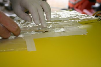 |
| Mainly 2oz was used, with a layer of 6oz cloth in the middle for strength. | 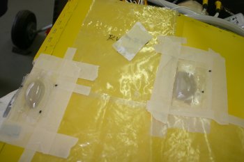 |
Mon 30 April 2007 | |
| To finish up I continued prep of the plenum diffusers ready for RTVing / pop-rivetting. | 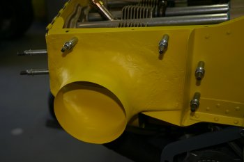 |
Tue 01 May 2007 | |
| Then onto RTVing the plenum entries - new skill / material to learn about. Seems to be a bit like 'thin pro-seal' - but the key is not worry about the excess, just peal it off later once it is dried. | 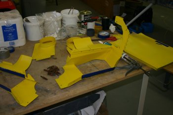 |
| RTV went better than I expected and put it back onto the engine to set over night. | 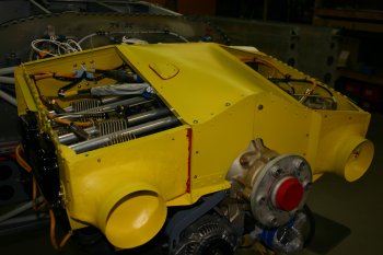 |
Wed 02 May 2007 | |
| RTV'd and riveted the plunum 'bubbles'. | 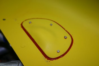 |
| The forward center locaiton of the baffle / plenum had significant gaps - RTV seems to fill them well, although it will be interesting to see how it holds up to use. | 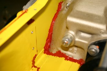 |
| Also sealed the lower inter-cylinder baffle - not pretty but should work. | 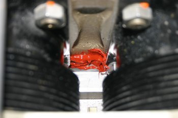 |
Sun 23 September 2007 | |
| Finished off the day doing some RTV work on the upper seal of the plenum. | 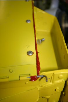 |
Tue 25 September 2007 | |
| After lots of cleaning, I re-did the RHS top plenum cover RTV - seems better, but I'll let it set well this time..... | 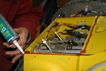 |
Fri 02 November 2007 | |
 | |
| Home | Carl Morgan | Previous|Next|Latest |