Undercarriage |
|
| Therefore we moved onto yet another new area - the undercarriage. | 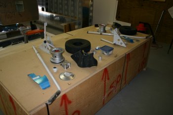
|
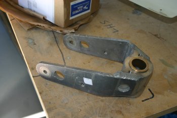
| Dad started work on the top part of the gear legs whilst I worked on the lower end. We also split things left leg for me, right for him. This is the weldment that has to go up against the spar for the main right leg. | 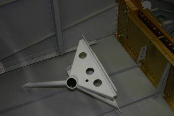
|
| Quite a bit of finishing work is needed on the powder coated parts to make them fit. Cleaning up the edges and carefully scotchbriting the ground parts to easy the fitting. | 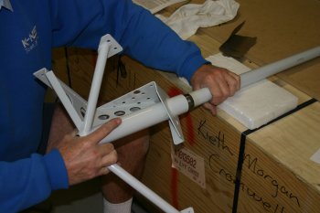
|
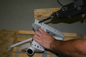
| Then match drilling of the parts. I was a bit nervous about this as the ground parts have really nice close tolerance fits on standard bolts but a drill does work - just follow the instructions (again)! | 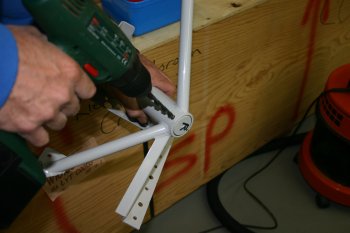
|
| The last piece of preparation for the hole cuts is to remove the temporary stand as this uses the spar for support and the gear legs need to take priority. A simple box / saw horse does the trick. Dad also worked on a template and is ready to go tomorrow morning. | 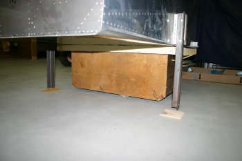
|
| I got stuck into the lower assembly. The first thing on the list was the brake bracket. This has to be opened up slightly for the powder coated mount. No easy / good way of doing this so I ended just using a scotchbrite wheel in the diegrinder and carefully checking things as I went. | 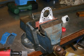
|
| Next up were the spacers. Yet again I miss not having the lathe running yet. I may come back and redo a lot of these 'properly' but the current results are probably fine and fit for purpose, we will see. | 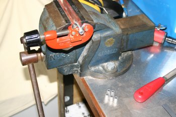
|
| This is the basic inner section of the wheel bearing (NOTE: The brake mount is on the WRONG way round in this photo). The plans are really poor for this area, a decent exploded ISO would make life SO much easier. The gear leg needed scotchbrite 'reducing' a little to get everything to fit. Hint: The close tolerance cross bolt is in bag 1068. | 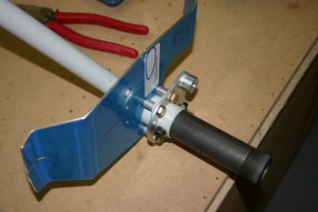
|
| Next up I started on the left wheel. First remove the three bolts and split the hub apart (a 'gentle' tap is needed). | 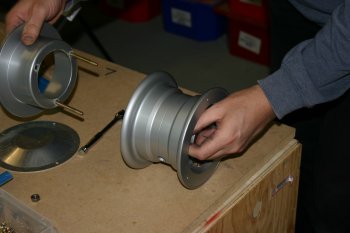
|
| Then apply talc to the inner of the tire for 'lubrication' and insert the tube and then outboard hub side. Don't thread the tube valve through the hub until after it is inside the tire - it doesn't work (don't ask me how I know!) | 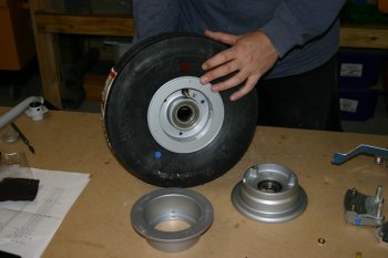
|
| The reverse side, ready for the inboard hub. A little air is in the tube at this point to help seating. | 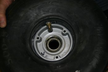
|
| The completed wheel assembly. The bolts torqued to about 90 ins-lbs and the pressure nice and low around 10 PSI for current working. Tomorrow I'll worry about fixing it to the axel! | 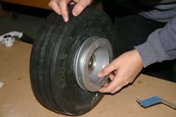
|
|
| First thing this morning Dad did the right hand wheel. I'm sure he was more efficient than I, but same net result. | 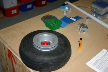
|
| I continued with the left wheel and finished the assembly off. It is now ready for the upper weldment to attach to a fuselage. | 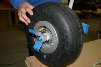
|
| For the rest of the morning I sorted the right hand wheel assembly. Same deal as the LHS, open up the brake mount with the scotch brite wheel. | 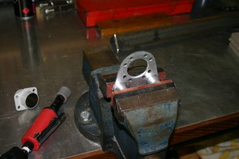
|
| Cross drill the axel for the close tolerance hex bolt. | 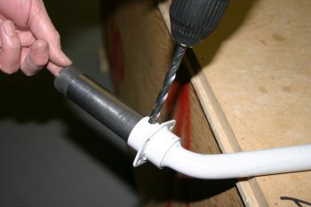
|
| Grind the washers for the sleeve mounting so that it doesn't interfere with the brake mount. | 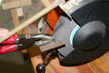
|
| Assemble axel parts. Things in real life aren't quite that simple. I had real problems getting the wheel pant support bracket (the AL sheet covered in blue plastic) to sit straight. A bit of investigation and opening up the brake mount a little more (only fractionally) and the bolts were all perpendicular to the mounting. Hint: The spacers do need to be slightly large than the plan call out to give spacing for the brake disk / wheel pant support. I used 1/2" to start with and the gap ended up as 5/32" all round. | 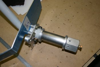
|
| The completed gear legs (lower sections). The wheel fairings work has to come after mounting them onto the fuselage. | 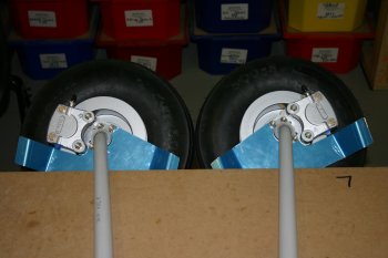
|
| Meanwhile Dad started work on the cut outs. We are taking the opportunity to practice on a scrap fuselage (don't ask) so hopefully the real thing will be an even better fit. | 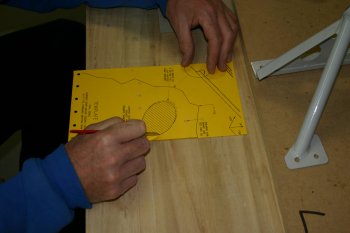
|
| Hole saw was used for the first major cuts. | 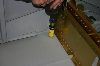
|
| Then back to scary tool #2 (rotary burr) to shape the hole further. | 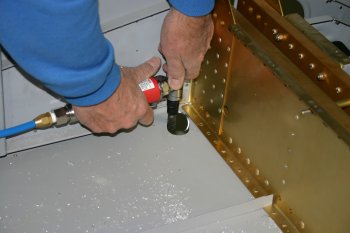
|
| Finishing with a file for the final tidy up. The results were pretty good and I took a template for my attempt on the right hand side. The hole ends up being significantly bigger than the template give by VANs but it will all be sealed and under cover. | 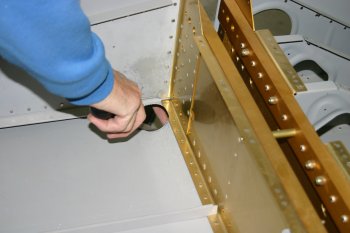
|
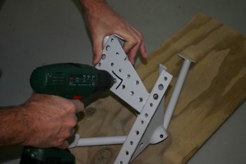
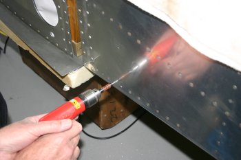
| Dad also ran a drill to clean off the powder coating from the gear leg weldment. | 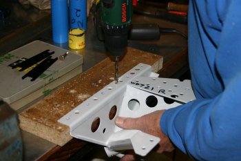
|
| I continued with the LHS gear leg, match drilling the fuselage / leg mount. | 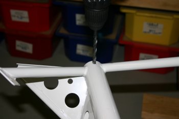
|
| I then started the LHS cutting. This is the template from VANs. A pilot hole was then drilled up into the cockpit. | 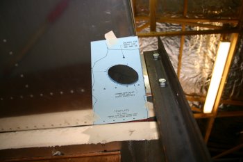
|
| First a single large hole saw in the center of the cutting. This used the pilot hole drilled from below. | 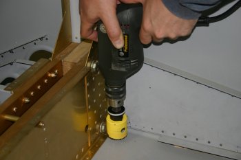
|
| This is the weldment without further shaping. | 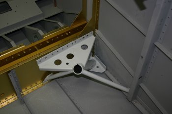
|
| The cutting might be big enough for the end shape, but not big enough to get it through / manoeuvred in. | 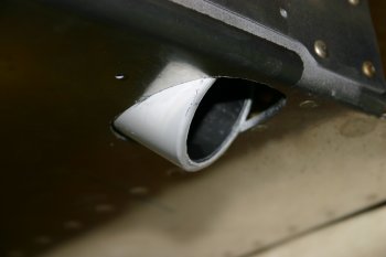
|
| After much shaping (rotary burr again) this is the final product. The outboard (hidden) spacing could be a little tighter but the inboard is about as tight as possible (this is quite a bit bigger than the VANs template (1/4"+ in places. | 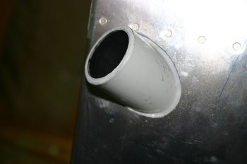
|
| Whilst I played with the fuselage, Dad set to work on the front wheel. | 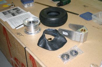
|
| This looks pretty simple, however not pinching the tube and getting the tire to sit properly on the hubs is not easy (to say the least). Start with lots of French chalk to aid in lubrication. Don't use soapy water as the chalk will 'set'. | 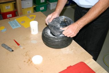
|
| Get the valve hub and tube into the tire and inflate slightly. | 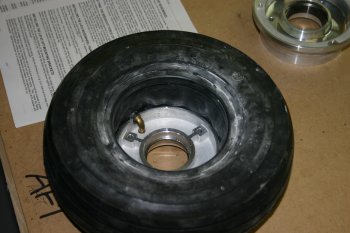
|
| Use some longer AN4 bolts to help align the hub sides. Then work around the hub bolts with just the bolts plus nut (no washers) to get the basic alignment. AT this point you still want 1/8" gap between the two halves. | 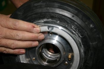
|
| Then inflate slightly (< 10 PSI) and make sure the valve is seating properly. | 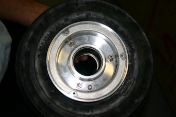
|
| Check the tube hasn't been trapped between the hub halves. This can be done by touch or with a little mirror (or both!). | 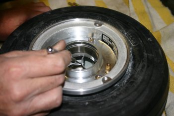
|
| Then change one bolt at a time, replacing with washers and lock nuts. Then pump up to ~ 30 PSI whilst checking inside for trapped tube. | 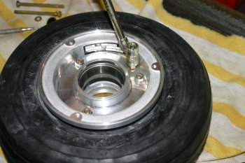
|
| Then torque up the hub bolts. | 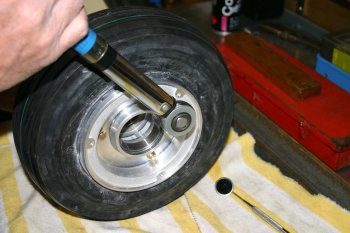
|
| And inflate to 60 PSI. The tires should 'pop' onto the hubs and then leave overnight to see if any tube damage has occurred. I'll let you know tomorrow! | 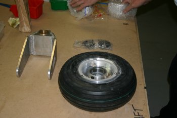
|
|
| First thing I finished the preparation that I could for the front wheel. The drawings for the nose wheel are better than the mains, however there is still a bit to be desired on the labelling / call outs. | 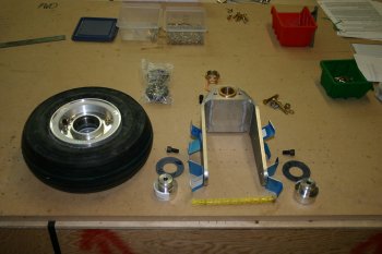
|
| Cross drilled the front leg mounting. | 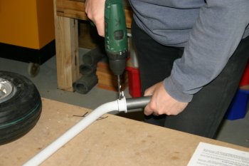
|
| The cross bolt from the plan call outs is for a AN5-17A but it looks too long to me. I don't have to rush to make a decision but will probably get a 16A to replace it. | 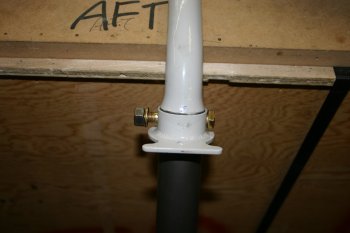
|
| This is the brake disc / wheel pant support. The gap ended up being 1/4" rather than the 1/16" suggested, hence why the spacer were slightly larger (1/2") than the 13/32" suggested. | 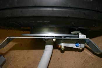
|
| We then dis-assembled the main gear legs and re-oiled all the ground metal surfaces for long term storage until the new fuse arrives. | 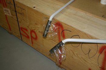
|
|
| | 
|
| | 
|
| | 
|
| | 
|
| | 
|
| | 
|
| | 
|
|
| | 
|
| | 
|
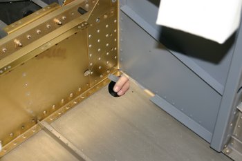
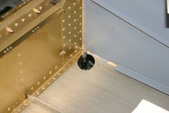
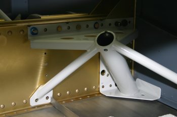
| Still VERY frustrating. The weldment is still not sitting properly against the spar, and the bolts are exceptionally tight. Not sure of the path forward...... | 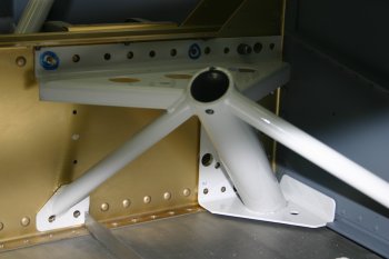
|
|
| | 
|
| | 
|
| | 
|
| | 
|
| | 
|
|
| Dad got a couple of hours this afternoon to start looking at the gear mount again. Making slow progress but things seem to be lining up well. Some of the weldment bolt holes need a little work but I'm sure he will sort it. | 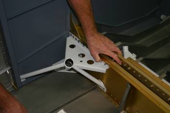
|
|
| Dad continued with the gear weldments and trying to get everything to fit / pull down properly against the spar. | 
|
| Dad then took the scotch-brite wheel to the rear edge of the undercarriage mount. | 
|
| | 
|
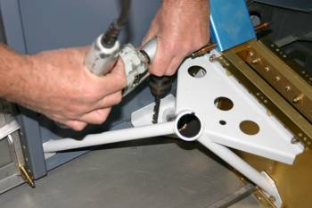
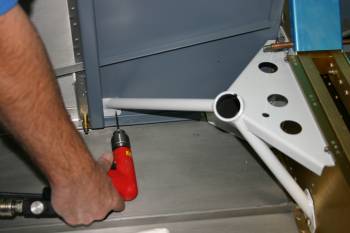
| Dad continued with the spar / weldment alignment. | 
|
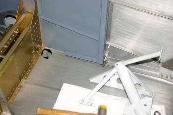
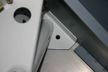
| The lower inboard bolts are particularly difficult as the floor stiffeners and weldment. | 
|
|
| | 
|
| | 
|
| | 
|
| | 
|
| | 
|
| | 
|
|
| First thing today was to de-rig the wings so that we can continue with the various sub-system independently. | 
|
| Meanwhile, Dad was looking at the gear weldment. The first set of bolts to be drilled were the lower 5 directly in front of the spar. | 
|
| As per usual the VANs design works well, although the gear weldments are a little 'imprecise' , the basic configuration works well and the edge distance looks fine. | 
|
| The next problem was the forward weldment brace. Access to the forward location is prevented by the vertIcal J structure. | 
|
| Therefore rather than trimming it (which we did consider) Dad marked out the outside skin and drilled into the fuse. This was a 'calculated risk' which panned out fine, but working out the location was tricky. We basically used the distance plus a horizontal line from the first bolt / cleco location. Then the holes could be opened up slowly. | 
|
| The rest of the undercarriage work was fairly simple, just opening up the locations to the correct sizes. The multi-skinned AL + steel did cause the drill to grab quite a bit. | 
|
| Dad finished the day with removing the gear weldment from the spar. Lots of cursing and muttering about knuckles and skin being lost...... We need to get a long reach 7/16" spanner.... | 
|
|
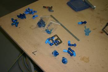
| Dad worked on the brake line unions and fixings. The lower surface (fuselage skin) needs to clear the shoulder of the 45 degree union joints and the weldments is what it all tightens down onto. | 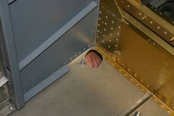
|
| Dad continued with gear weldment and specifically the brake union. | 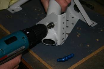
|
|
| Dad was still working on the weldments, particularly the lower spar bolts. | 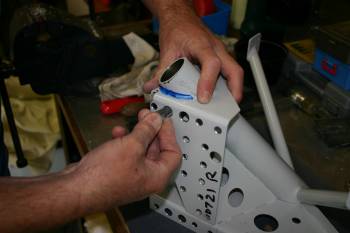
|
| Just to tidy the exposed steel, a little red-oxide primer was used. | 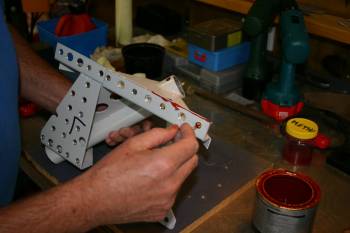
|
|
| This time the 'persuasion' needed was slightly less than last time. | 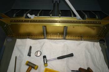
|
| Then Dad got to continue fighting with the gear weldments! | 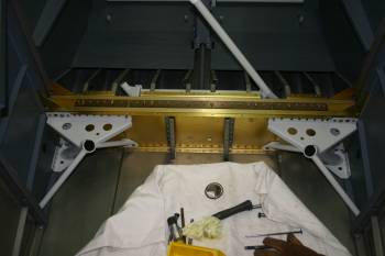
|
| Dad worked his way round the various nut / bolts and started trying to pull them all up. We decided to use 'real / new' nylock nuts (for the non-spar bolts). | 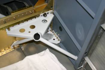
|
|
| I helped Dad with the gear weldment bolts - a bit tricky to get to and time consumming. | 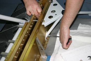
|
| Several of the lower AN4 bolts seem a bit short, we replaced the main inboard lower weldment bolts with 13's and used a -L washer on the strut. | 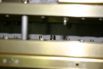
|
| We still have a problem with the inboard most lower bolts, the weldment prevents the bolt head seating properly. Options include heavily shaped washers, shaping the bolt head or weldment shaping. Not sure of the best option at the moment. | 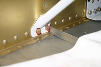
|
| An observation that with the gear weldments tightened up it doesn't actually sit on the lower skin, there is about 1/16" gap. The hole could be tuned further but easy to say after the event. | 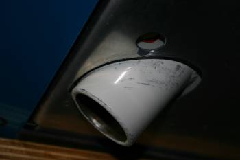
|
| After dinner I rigged the main and nose wheels. Hopefully we can get the fuse onto the real gear so that brake lines can be rigged. | 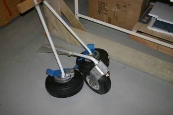
|
|
| | 
|
|
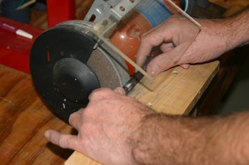
| Meanwhile Dad continued to fight with the gear weldments. The outboard bolts of the lower inboard brace wasn't seating properly, so we decided to grind a little material away to enable proper bedding down. Slow careful work. | 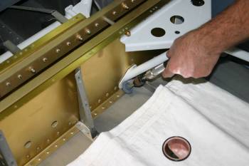
|
| Then a bit more 'red-oxide' primer / protection | 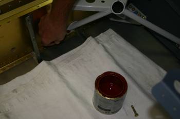
|
| Then the remaining gear bolts were sorted. A few washers were replaced with -L's to provide some thread through the nylock nuts but otherwise just awkward. Dad also made a useful low-profile 1/4" wrench. This could then be used with a spring balance to torque the AN4 bolts up to 60 ish inch-pounds. | 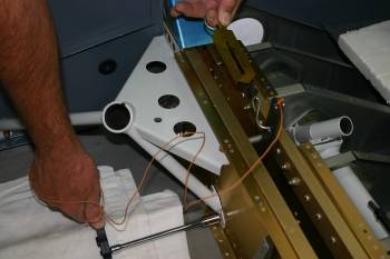
|
|
| We had a half today on the project, (some R&R first thing) and decided to have a look at the undercarriage mounting. First up we tried using the main gear weldments for the strop but couldn't get enough elevation of the fuse. | 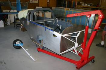
|
| After moving the hoist point forward to the main engine mounts, and removing the wheels from the gear legs, everything fitted. | 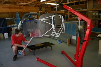
|
| Wheels on, supporting its on weight, however as the fuse / empennage is only a small fraction of the total completed weight the gear legs don't "bend much" and therefore is pretty useless as a platform for working on. | 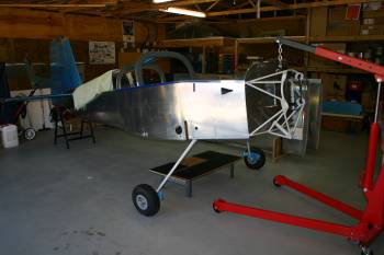
|
| But before we removed the legs, we started bending the brake lines that go down the gear legs into the brake callipers. | 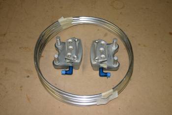
|
| Tube work is very new to me, however Dad has some background experience, first thing was using a flat surface to 'un-roll' the coil. | 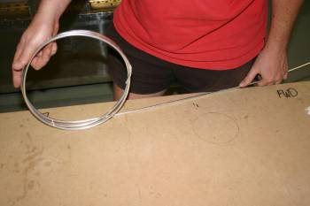
|
| I used a old pulley along with a bending spring, the basic shape is nearly a full 360 circle. | 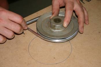
|
| The right leg solution worked well, although the 'loop' is a little larger than I might like. | 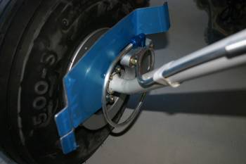
|
| The left leg was much better, yet again second time easier than the first. We will worry about the upper junctions tomorrow. | 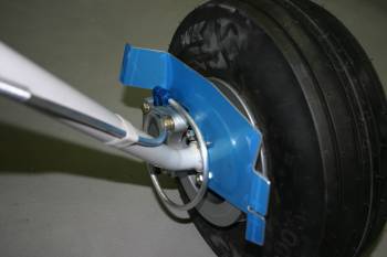
|
|
| I continued first thing with the brake lines. Both the tops were cut / flared after sorting the split plastic tube spacers. | 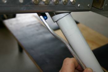
|
| The completed the lower leg of the brake lines, not sure if the clearance is going to be enough for fairings (see below) but good to start with. | 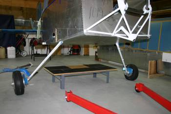
|
| I went on to a different area - main wheel fairings. These have to be mounted / aligned whilst there is no weight on the wheels (ie. the flying position) but I think that could get progressively harder as more parts are completed / installed. Therefore a first cut was started today. The first step is to mate the forward / aft halves of the fairing. This is tricky as there are no reference lines for any of the 'planes'. ie. no longitudinal, lateral or 'yaw' markings. I used a combination of hand file and sanding belt to get a reasonable fit. | 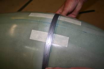
|
| Once everything was looking OK, I re-taped the two parts together and then used a line to give a center location (top & bottom) which helped considerably. | 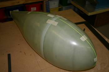
|
| Then it was drilling / celcoing and opening the wheel hole shape. This is all very emperical, eye line based etc, looks like it should work OK. | 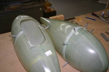
|
| Then rotar burr to open the shape in combination with air file and cutting disk. | 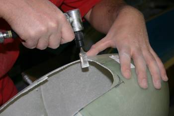
|
| A suitable 1" spacer (bucking bar) was used to locate the top of the fairing and the inboard edge progressively trimmed to fit. | 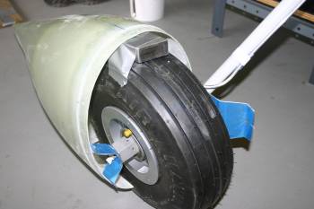
|
| By the end of the day I had a first cut mounting of both forward and aft halves, although the clearance on the brake line seems to be a problem. Until we get some proper alignment going of the aircraft / wheels it is going to be difficult to know how bigger problem the interference is going to be. | 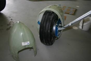
|
|
| Another day, another wheel pant. Basically, the left is the unmodified version, the middle is what we want, the right is the tools available..... | 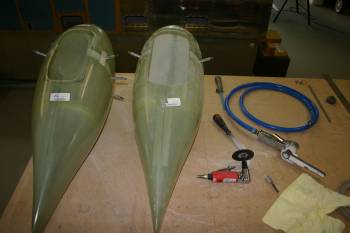
|
| The cutting wheel is simple and quickest method to start with, then the rotary burr. | 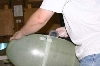
|
| Then re-organise the LHS brackets and test fit. | 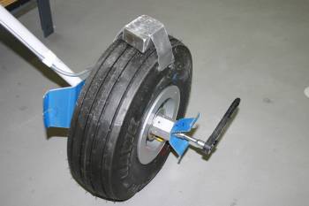
|
| The initial fitting looks OK, although we will wait until later for final fitting. | 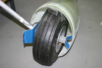
|
|
| And top coated front fork. This is now ready for assembly and filling with grease, one more bit to tick off the list. | 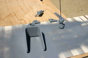
|
|
| The brake lines are generally easier as they are smaller, just feed the tail into the outboard side and route the lines forward. | 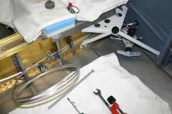
|
| We are using the brake valve option so I started making a new doubler plate. | 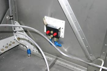
|
| The finished setup ready for flaring. I'm considering adding a plastic sleeve to protect the exit just below the heat box. More thought needed. | 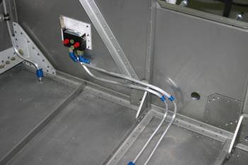
|
| I also fabricated the angle support that provides the end stops. | 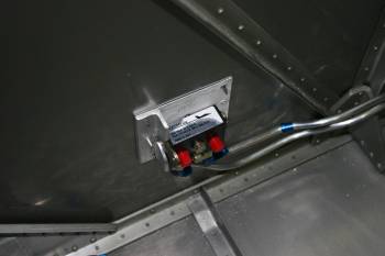
|
|
| I decided to go with a little sleeving over the brake lines. I also finished cutting and fairing the lines and fuel vent lines. | 
|
|
| Dad got multiple smaller jobs done today. First up was the fuel line vents. | 
|
| A cutting disk in the lathe did the job and then the rough edges were turned down. | 
|
|
| We focused on various bits today, the undercarriage was extracted from storage and taken back apart. The tires needed re-inflating, and re-oiling. | 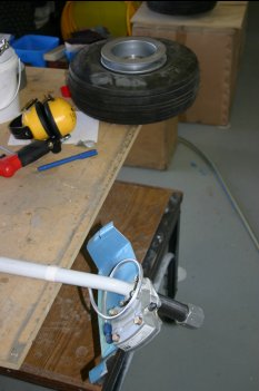
|
| Once we got the two main axles installed. the outstand work was the cross drilling for the main nut. After reading about Dan C's problems, I was a little nervous about the drilling, I ended up using a long #30 drill to do the upper location. | 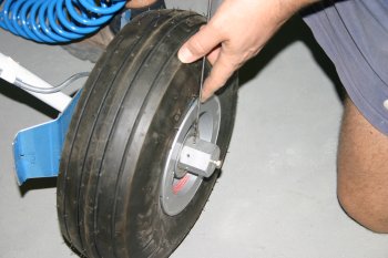
|
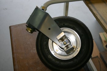
| Then removed the nut and wheel, this meant the angle drill could then be used for the lower location. Ended up working really well, and the tidying of the thread was almost a non-issue. | 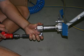
|
| | 
|
|
| Dad also re-did the 6 undercarriage spacers, this time out of stainless steel, hopefully this will reduce wear / fairing on the wheel pant. | 
|
|
| Dad also spent a few hours working on some gear stands that can be jacked up - more photos once complete. | 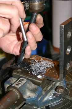
|
|
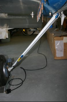
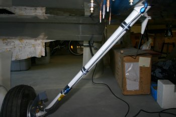
| Dad finished the axel jack lifts - work well. The idea is use these to lift the fuselage on the gear and then prop up the wings under the tie downs. Another item to add to the maintenance kit. | 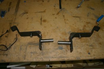
|
|
| | 
|
|
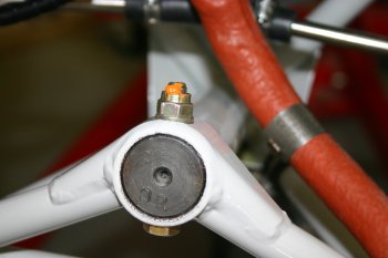
| After reviewing some of the problems others have had with the nose gear and vibrations etc, I've taken a lead from Roberta and copied her idea. Dad made a jig and provided a location that can be held behind the nose gear fairing mount and still in the bulk of the AL stepped bush. | 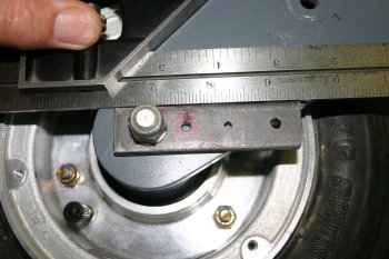
|
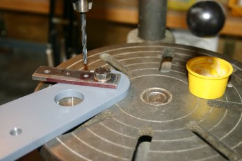
| Some careful measurements on the depths and pillar drill sorted the locations. | 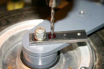
|
|
| Dad continued with the nose gear bushing mod - tapped the large AL shoulders for #10 screws. | 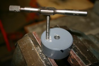
|
| Finished result - now the main bolt can be tightened / worked on without affecting the bearing seals / bush rotation. | 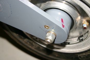
|
|
| | 
|
|
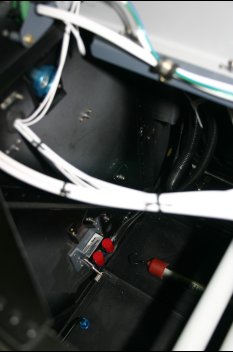
| The B nut on the brake valve and angle bracket mount were a pain to install with the sound proofing. | 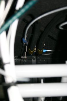
|
|
| Our plan is to use flexible brake lines rather than the VANs AL 'loops' at the base of the gear leg. First step was to split a spare high pressure hose that I had. Tape, mark and die grinder. | 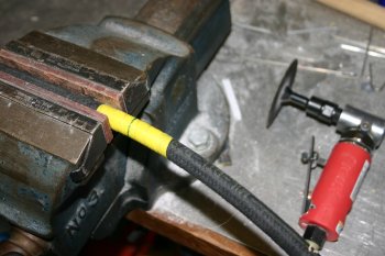
|
| Then thread the 'outer' section onto the pipe and make a mini mandrel out of a spare union / nipple. | 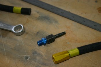
|
| Lots of lubrication, a bit of grunt and final trimming / cleaning of the internal path. All clear and has pulled down well, difficult to pressure test locally, but I'll test with brake fluid later. | 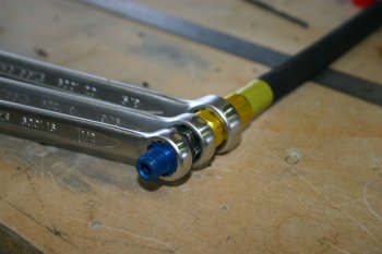
|
|
| Bitty day - I did try my first bit of MIG welding - a couple of chock blocks for the main gear - came out well..... | 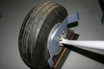
|
|
| VANs have issued an a new service bulletin for the nose leg. This is potentially a real problem / delay for us - I'm feeling pretty down / defalted about the whole thing -
the delay of shipping stuff back and forth to the USA (and over Christmas season) not to mention the cost being fully passed onto the customer. Not sure if I need to cancel / move
the hanger plans yet.... a stiff scotch tonight!
| |
|
| Research and paperwork for the nose leg, also got an order into VANs - I wish they could understand the concept of international shipping..... Jim Talbot (7A builder) also poped in during the afternoon. | |
|
| | 
|
|
| | 
|
| | 
|
|
| | 
|


