Wiring |
|
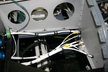
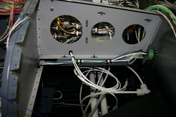
| More wiring - still trying to work out the path through the main spar for the various wing and aft fuselage components. | 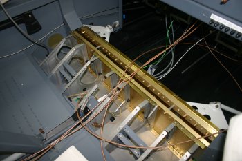
|
|
| Then back to the wiring! Jeez it is slow, trying to plan how to get all the cabling from the front panel area through the spar snap bushes to the wings and rear elements. We are getting closer to a plan, but I'm sure it will need tweaking further as we go along. | 
|
| The main mid-RHS location now has the 5 x audio 3 pair cables plus the GPS1 and COM2 coaxes - tight but works. | 
|
|
| I was still on the wiring - slow progress, lots of inter-dependancies. I'm trying to keep the audio cables, strobe lines, main power and antenna lines seperate as much as possible - not a simple problem. This is also an area where other website / builders are of limited value and there isn't that much information available. | 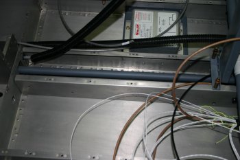
|
|
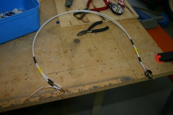
| The AutoPilot wire bundle from SteinAir is 2 power + 5 signal cores, however the pitch servo requires an additional core for the trim sense - Dad added an extra 'white 22AWG' to the bundle - just get the twist in the right direction. | 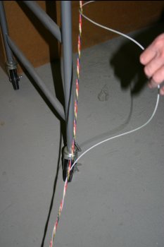
|
| After more thought / layout, we decided to remove the Adel clamps in the rear baggage floow section and go with 3 conduits instead. | 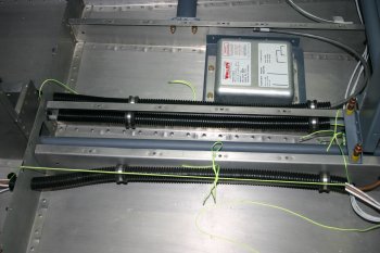
|
| This is the forward side of the spar in the center tunnel. I'm starting to get a little concerned about the amount of wiring that has to go under all the fuel pump and associated components. | 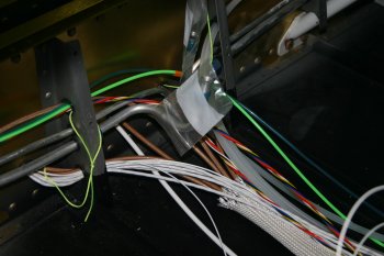
|
|
| Both sides of the tunnel will have cables / lines going down them - a couple adel clamps will hold everything. I gave up trying to leave the elevator push rod installed, disconnected it and used NAS #8 bolts rather than screws. | 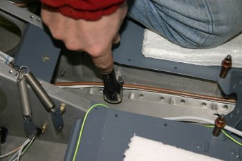
|
|
| Only a few more cables laid today - pitch servo bundle and nav lights. | 
|
|
| I've been trying to work out a neat way of providing a connections in the mid section between things like the trim / position sensors, stick trim control, nav lights power wiring. | 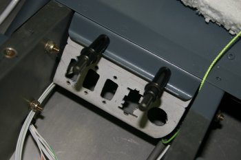
|
|
| Continued with the wiring - wing feeds for lights. | 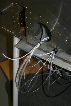
|
| A number of areas need multiple feeds of the same line (eg. signal ground). | 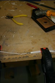
|
| After some experiments using crimps and research I decided to use Bob's recommendation and wrap and solder. This is only for low power signal control, for real power I'll use pin crimps. | 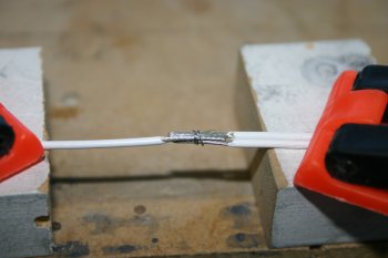
|
| Obviously the important thing is to make sure the solder doesn't wick up the wire and result in a frature point. The whole joint was then covered in clear heat shrink. | 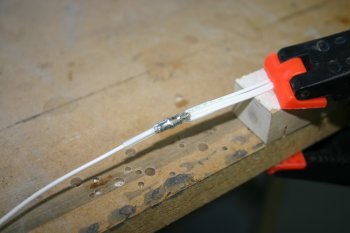
|
|
| Short day with other things on - I did manage to sort the Vref feeds for the position sensors for the GRT analog lines - 1K resistor inline with a regulated feed - not sure yet whether we will use 12V, 4.8V or ship power. | 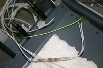
|
|
| More wiring - I decided to redo some of the tunnel layout and added the flap switch sense lines. Also started the numbering / id's on cables. | 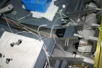
|
|
| I started terminating the mid ship ground cables. Dad drilled (wrongly) and then remade a new ground strap..... | 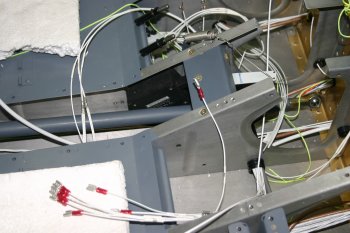
|
|
| Also sorted the strobe pack plugs. Note the cable screens have been extracted and commoned to the chasis. The inbound ground crimp is doubled up for the left side. | 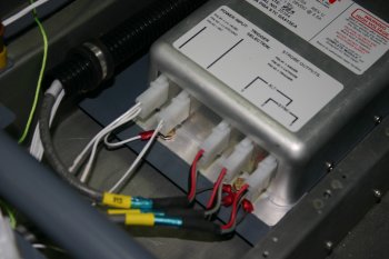
|
| The ground tab was bolted up and documentation updated. Documentation is a significant part of this process, obviously it is just part of the long term investment from a maintenance perspective. | 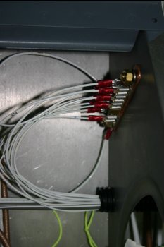
|
|
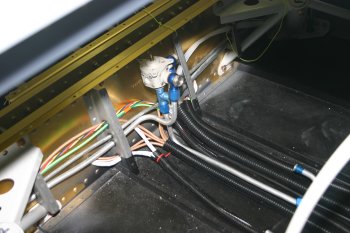
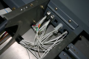
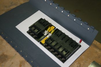
| Sorted a couple of adel clamps and the upper C chanel power connectors for the internal baggage light. | 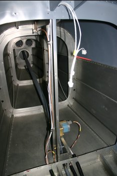
|
|
| | 
|
| | 
|
|
| | 
|
|
| Short day with other stuff on. Dad did some shopping for bits in Dunedin, I was doing documentation, order planning and sorted the panel end of the contractor control leads. | 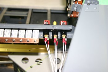
|
|
| More wiring - working mainly on the feed / firewall penetration routes | 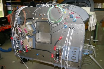
|
Still working on the layout of the various 'boxes' for the systems. I would like to have them all accessible from the upper panel if possible, but it is going to be difficult. To locate are:- FADEC HSA
- FADEC Serial Bus Controller (SBC)
- AoA
- GRT AHRS
- B & C Voltage Regulator (SD-20)
- NAV 1 diplexor
The side ribs are option, but access will have to be under the panel which will be difficult. | 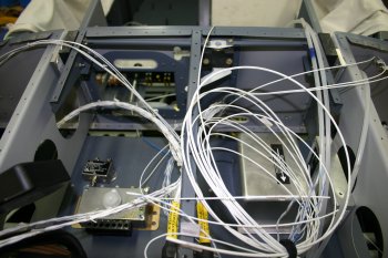
|
|
| Started by un-picking the audio panel audio leads. We wanted long leads in the harness, but somewhere along the lines between Stein and Stark the information got lost, so I'm redoing those pins directly. | 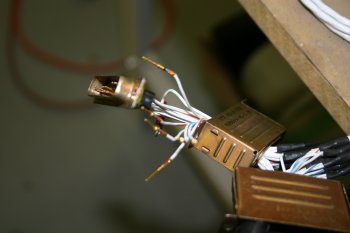
|
| More thought on 'box layout' - this is the current best plan. The biggest challenge is the B & C voltage regulator - it is a strange shape for mounting and requires access for adjustment on the 'other side'. | 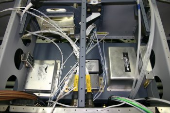
|
|
| Rest of the day was spent laying / labeling and terminating 18 additional wires from the panel to the seat joint. | 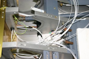
|
|
| After a re-check of the labelling / functions, I shrunk all the heat shrinks | 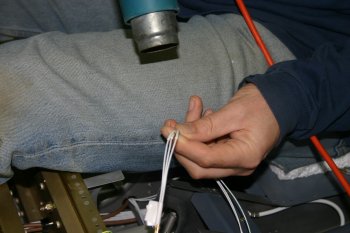
|
| and terminated the pin locations. Various other bits done, starting working on the grips - and increasing the hole size after my ordering mistake. FADEC harness prep and tunnel tubes also worked on. | 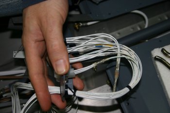
|
|
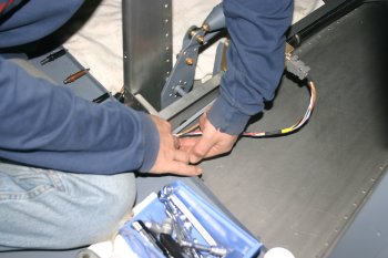
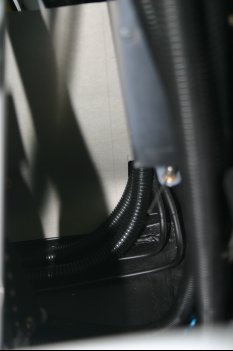
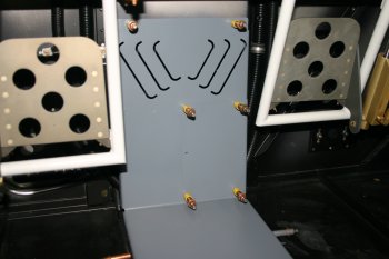
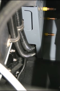
| I started with some bits - re-installed the 4 adel clamps in the main tunnel - fiddly but simple. | 
|
| Then tied up various cable bundles with lacing cord, I'm using lacing rather than plastic wraps - a little more work, but light and simple. | 
|
|
| | 
|
|
| | 
|
| | 
|
| | 
|
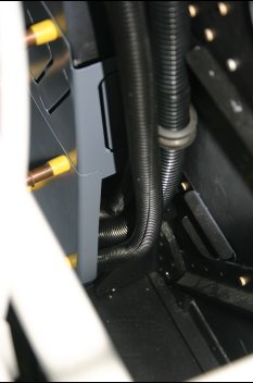
| | 
|
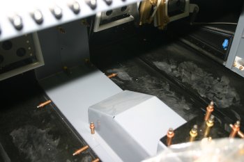
| | 
|
|
| Dad spent the afternoon working on the FADEC cockpit harness - mainly un-picking, trimming and re-terminating the power leads, plus the labelling and documentation updates. | 
|
| I was working on the avionics stack harness. As supplied few of the GNS-430 data lines are exposed, so various connectors needed to be openned up and extra cores added. I decided rather than trying to complete the harness in situ in the aircraft I would bring out the data lines as tails and have a mid connector between the radio stack and the flight instruments (GRT et al). | 
|
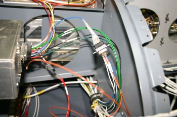
| One problem I spotted was a nicked wire (center of picture) - this wasn't us. Glad I caught it - could of been a real bear to find later - it didn't touch the core wire, just the insulation - I removed the pin and covered with a small piece of heat shrink. | 
|
|
| Dad and I worked through the FADEC harness which resulted in some quesitons - the actual harness doesn't quite match the published documentation. Questions have been sent to AeroSance. Update: The harness is correct, although it has 2 un-needed extra lines (Fuel Pump Light Lo, Power Sense B), the power pin layout documentation is wrong in places, but works as it should. | 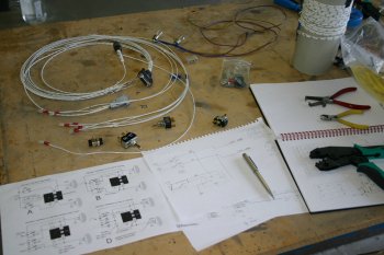
|
| Continued with various bits of wiring, currently considering moving the magnetometer cables to keep apart from the COM antennas - but it is difficult in the small space we have to work in. | 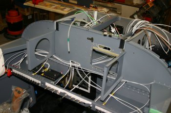
|
| Moving onto to the wing wag units I sorted some of the leads and setup a test rig to try the progressive Off,Taxi,Landing light + Wing Wag Off/On combination. Should work ok, but will need diodes to prevent back feed power through the wing wag unit. | 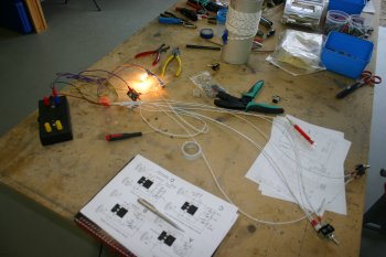
|
|
| More wiring - starting to work through the fuse A side (mainly lights) and lower bar switches. About 60% done in that area, slow progress but getting there. | 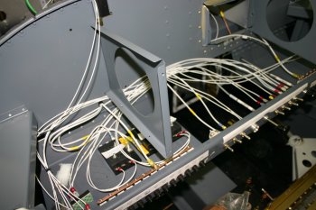
|
|
| Then back to more wiring - same 'photo' - different day.... Most of the non-avionics power wiring is now complete. | 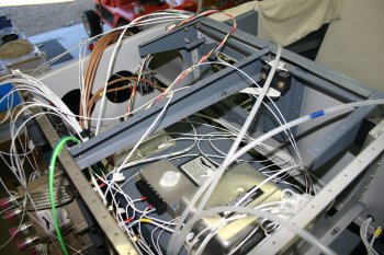
|
|
| Dad worked round the rest of the contactor controls and then onto the main feeds. The firewall means that once the both ends are terminated things become less flexible so we have spent quite a bit of time planning and making sure grommets and snap bushes etc are the right sizes..... | 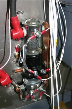
|
|
| Then back to wiring. Re-installed the FADEC harness and worked through routing, tying and connecting the remaining tales. I think most of the power connections are now provisioned, if not connected yet. | 
|
|
| Then routing, trimming and termination - same deal, different day. | 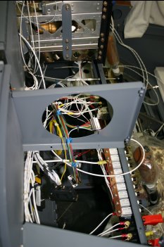
|
|
| Then back to more wiring..... GRT EFIS harness installed and Garmin power & ground lines terminated on fuse / breakers as needed. Getting close to a proper panel power up. | 
|
|
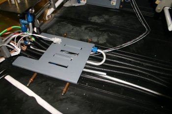
| | 
|
|
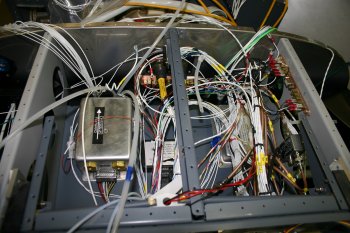
| | 
|
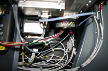
| | 
|
| | 
|
| | 
|
| | 
|
|
| | 
|
|
| More wiring, removed the panel to help get access to the lower cabling, a bit more tidying and bunching. | 
|
|
| More general wiring, re-installed the nav, strobe, wing light power / switches among other things. | 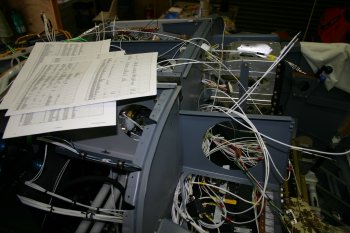
|
|
| I finished off the day laying the Push To Talk (PTT) lines plus grounds for the panel mounted buttons and also the AoA buttons. | 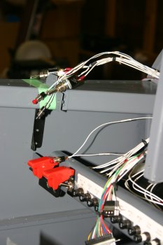
|
|
| We knew the conduit going to the rear of the fuse was too long, but rather than just cutting it off Dad tried a different approach and made a 'hatch' for the NAV aerial and trim lines and allowed the other lighting to continue after. Difficult to get a photo, but he used an old soldering iron bit to melt the hole. | 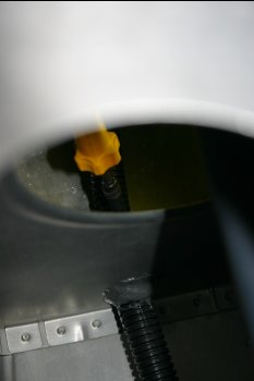
|
| The result before pulling the cables back through. | 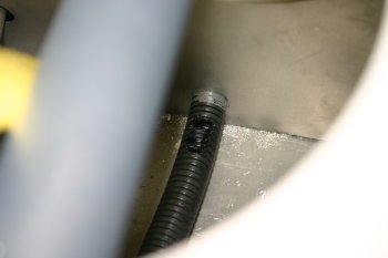
|
| Final result, the termination of the plugs can't be done until the rudder is mounted for the final time, but I may cut and prep just to reduce the trip hazard. | 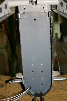
|
| This is the location for the new upper switches and dimmer controls, it includes the mute switch for the 'un-switched' audio input to the GMA340 and the buzzer feed. | 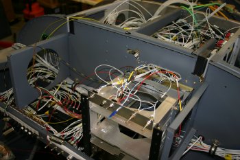
|
|
| Dad continued with the rear deck, drilled a route for the electric pitch trim wires and the BNC bulkhead fitting for the NAV1 aerial. | 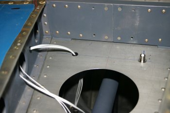
|
| I finished the fiddly wiring of the control switches and attached to the main harness already in the plane. | 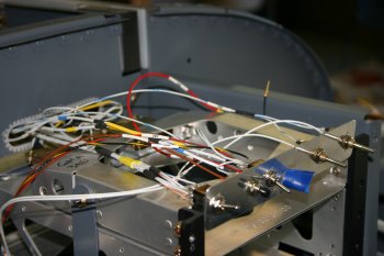
|
| Then onto finishing power feeds / controls for the dimmers. We are running really short of #20 wire which means I'm having to scavenge where possible. | 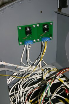
|
| and organised a route and retention for the NAV aerial to stop it vibrating. | 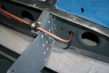
|
| I finshed by removing the RHS tray and did some layout / mounting of the flap and CO detector board. As per usual it took longer to think / plane than actually do. | 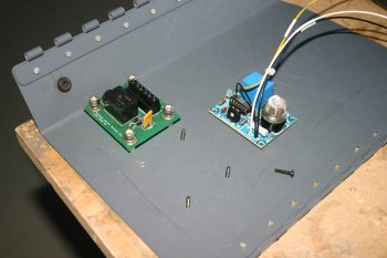
|
|
| After more talking / planning, Dad spent time fabricating this little bracket to hold the USB extension lead. This will provide a location for MFD 2's USB interface which is used to store the recorded 'demo' LOG files - I'm expecting to use it extensively during testing and maybe longer term also. | 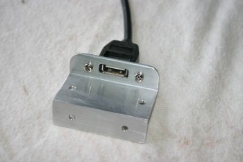
|
|
| Finished up some of the wiring for the A hot fuse and the mini B bus fuses (annunciator and voltage regulator feeds). I think this is the last of the power wiring, I'm sure I'll need to re-work some bits but good to be at this point. | 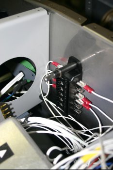
|
| A couple of hours this afternoon we worked through the annunciator leads - no PCB / LEDs to go on the end of the lines yet, but at least the majority have been checked out. Some outstanding questions with regard to the 10 degree flap status / AoA sensor and the 60 Amp ignition sense not working, more investigation needed. | 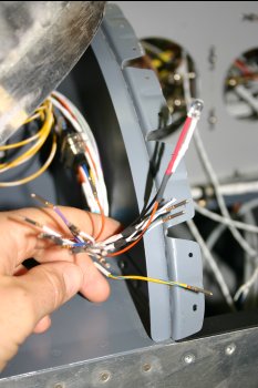
|
|
| | 
|
|
| | 
|
| | 
|
|
| | 
|
|
| Dad remade some of the fat wires and added heat shrink / labels. | 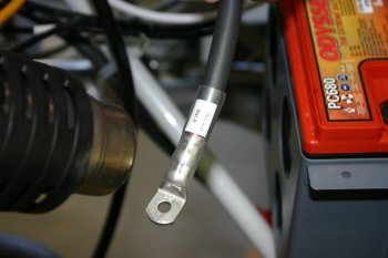
|
|
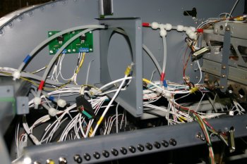
| The firewall fuseblocks are now mounted, the misc individual block also got heat shrink on the feed lines | 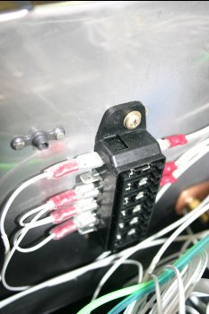
|
|
| | 
|
|
| | 
|
|
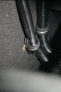
| This was the discovery of the week - I've been fighting adel clamps and trying to get bolts through them. After various discussions we came up with this - works a treat! | 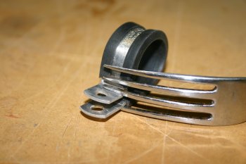
|
| | 
|
| | 
|
|
| | 
|
|
| | 
|
|
| ELT remote head wiring and music input. | 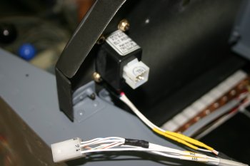
|
| Re-wired / re-threaded the P1 stick switch lines. | 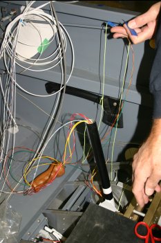
|
| Removed the EIS 'blue 4.8V reference' DB9 connector and converted it to a simple solder splice. | 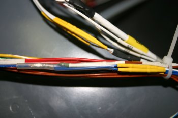
|
|
| Various bit of cable tidying and wrapping - we are trying to go round and reduce the chance of rubbing / chaffing where ever possible - particually in areas that are hard to inspect once final skins are on or areas which are 'feed' lines and have limited circuit protection. | 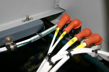
|
|
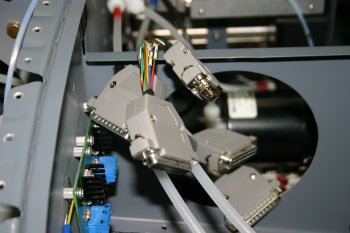
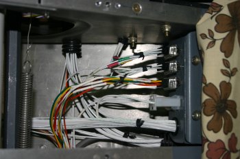
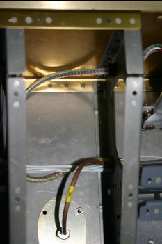
| I moved onto to starting the slow process of tieing / support all the wires / cables. I worked on the main panel area to start with. | 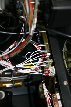
|
|
| | 
|
|
| | 
|
| | 
|
|
| I spent a few hours extracting tunnel cables - this were secure, but were going to rub over time on the lower skin rivets - not something that I want to replace / fix later! | 
|


