


 |
 |
 |
| Home | Research | Delivery | Empennage | Wings | Fuselage | Engine | Electrical | Tue 30 Aug | Thu 01 Sep |
Wed 31 August 2005 | |
| I continued this morning with the custom front access panels. Drilled the corners, then sabre saw for a rough cut. Then it was slow careful progress by file / scotchbrite finishing. |  |
| Then lots of drilling / nut plates. I decided to use #6 screws here and 'next time' I would use fewer screws! |  |
| Final step dimpling and prep'ing for priming. A few more parts to add to the pile. The weather is still too cold for spraying at the moment. |  |
| I sorted the forward end of the rear brace. I'm leaving the angle supports to roll bar locations until I've sorted the custom lower skin of the C channel. The plan is to use the void in the C chanel for a baggage down light and possible Video / Camera mount. | 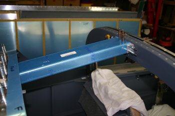 |
| You may have also noticed progress has been even slower than normal for the past few days and that is for a number of reasons - mainly my mind is focused on other family things.
Therefore I'm tending to work on smaller items that aren't quite so challenging - but still need to be completed.
The weather is already getting better - the last couple of days have been sunny with highs of 20 degree C, however today is offically the last day of winter! Therefore I'm not planning on doing any canopy cutting for a few weeks. With plenty of other items to sort I started looking seriously at the firewall forward area. | |
| The FADEC ECU's are mounted on the firewall with these bases. As supplied there are a lot of rough edges / corners - so it was the normal file / debur / scotchbrite process. | 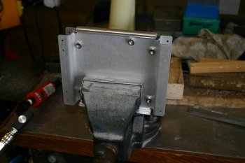 |
| Then I started unpacking some of the firewall parts. These are the low voltage harnesses from the FADEC system. | 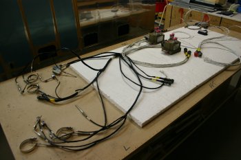 |
| Click for large image version This part of the harness is the low voltage part that is 'attached' to the physical engine. Each cylinder has EGT & CHT probes plus a solenoid to control the fuel pulse injection. The standard throttle body is replaced with a 'tube' that has a single butterfly valve plus a poteniometer and microswitch. This also provides a mount for the two independent ECU manifold air pressure and tempature sensors. | 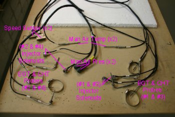 |
| Click for large image version The sensors above go into the main connectors which in turn go to either the firewall bulkhead connections or directly to the ECUs. The ECUs have an upper section which provides the high voltage 'spark' and a lower section with the 'inteligence'. Each ECU looks after two opposite cylinders. | 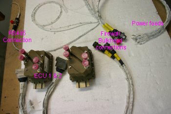 |
| Click for large image version The cabin harness provides the feedback / control systems. One thing I hadn't realised (but makes sense now) is all the power / ground supplies come through the firewall connector along with the other 'signal' information. The Serial Convertor (top left) provides a RS422 feed that will be converted and go to the EIS / EFIS system (yet to be ordered). Also there is a RS232 output that can be used with a PC program to record / monitor the engine during testing / use. The 'mag' control works the same as a traditional system - ground for 'off'. The fuel pump is controlled by a 3-way switch ON-OFF-AUTO, the FADEC system feeds the AUTO position and monitors for low RPM (<1000) and low pressure from the engine pump. The Health Status Annuciator (HSA) comes in two different versions - I went with the newer option which has just 2 LEDs (warning & critical). | 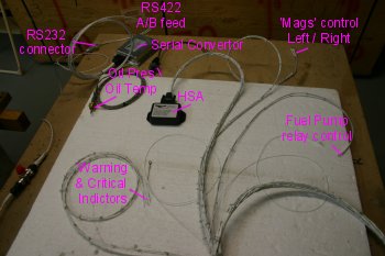 |
| The end of the day was spent unpacking and sorting firewall forward components. I seem to be missing / will need to get some pipe / manifold connectors. The Oil presure sensor is too large and I'm not sure which parameters any EIS will need specifically. Lots more research to do. | 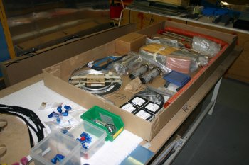 |
| Also it apears the #3 exhaust pipe has been damaged at some point which will need some re-forming. | 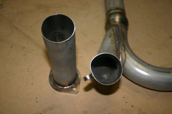 |
| Home | Carl Morgan | Tue 30 Aug | Thu 01 Sep |