Engine |
| This section is for the bit forward of the firewall. Engine, propeller, general firewall forward. Most of the detail will be in the next phase, but some testing / parts can be completed now. | |
|
| The actual engine has a plastic cover over it - not sealed, just stops it getting soaked in rain I guess. | 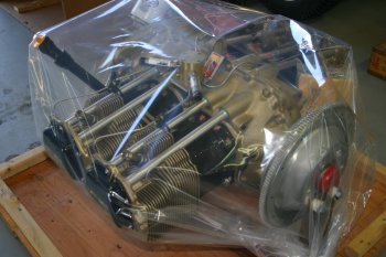
|
| The engine is mounted on the bottom engine mounts plus 2 prop bolt locations. This provides a good shipping configuration, but also provides good access around the engine before it gets mounted. Lots of sorting and organising engine information, and a quick review of the manuals. | 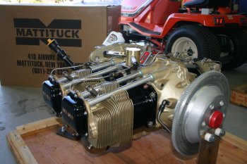
|
|
| Then with a second pair of hands around we started looking at the engine mounting / spacing. | 
|
| For those that get a Mattituck shipped engine (sensible people) the trick to getting the rear / lower bolts out is to raise the nose to unload the steel supports. Otherwise it is very difficult. | 
|
| After a bit of juggling we got the oil filter and governor line in. There is more space than I expected, however I suspect it will be pretty tight by the time we are finished. | 
|
| Some various photos for the rear space with the baffles. From the upper RHS. | 
|
| Behind from above. | 
|
| RHS side view. | 
|
| We parked the engine back on the stand before leaving for the day. I think probably the next step will be to mount the engine to the frame and then put the frame on and off the fuselage. | 
|
|
| Today was a big day from a morale perspective. We planned to mount the engine. The Lord mounts have upper / lower & fore and aft parts. I just laid everything out carefully and then got them checked. | 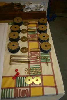
|
| The engine mount is something multiple people have multiple ideas about.
The 'VANs method' is to locate the lower points first and pull the egine back into the top points.
The 'Mattituck / Cal method' which I saw demonstrated in July in New York is to do the upper points first,
then drop the bottom ones in. It was a toss-up between them, but I went with the 'Cal' method as I had
seen that demonstrated. | 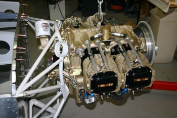
|
| Get the fuselage level and the engine also level. Push up to the mount and position the top bolts. | 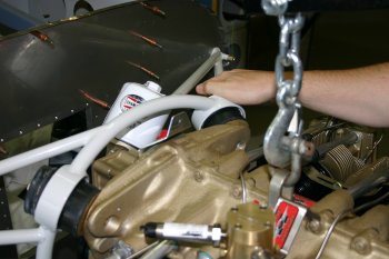
|
| Then 'wiggle' the top mounts and get the bolts started. | 
|
| Then position the lower mounts and lower the engine into the slots. The lower bolts were then drifted quite easily. | 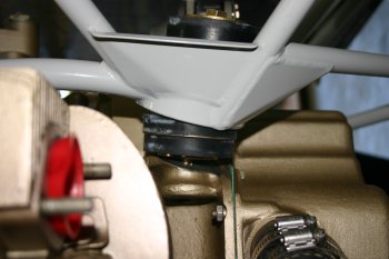
|
| Then tighten all the bolts and it is done. | 
|
| The finished result - about 30 mins start to finish. I'm sure it can be a real pain, but having seen it done before definitely helps. | 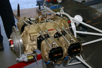
|
|
| Re-visited the engine mount bolts. The top bolts / nuts weren't in a position that the locking split pin was going to work. Therefore an extra washer (2 in total) was added to both locations. We also reviewed the SD-20 secondary alternator mounting and governor mounting. One problem is the studs for the governor mounting don't seem to have the right thread on them. | 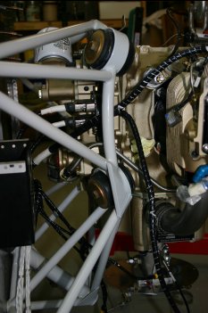
|
|
| Latish start with other commitments first thing. We removed the engine from the fuselage by undoing the 6 bolts that hold the mounting frame on. This worked REALLY well and I would recommend it as a method for getting the engine 'mounted' but still maintaning access to the rear area. | 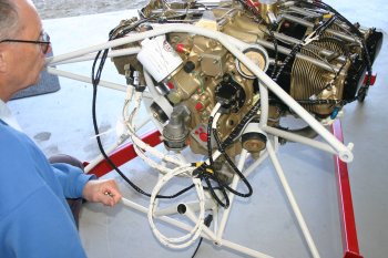
|
| After a email message with Mattituck I found out the govonernor studs are meant to be different and the longer 'wrong' threads where actually right for the pad threads. They are quite tight to get in, but a bit of EZ-Turn and take it slow and all was fine. | 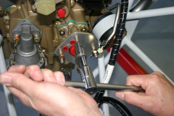
|
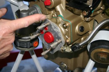
| Then it was a grease and prep the gaskets and mount of the governor. | 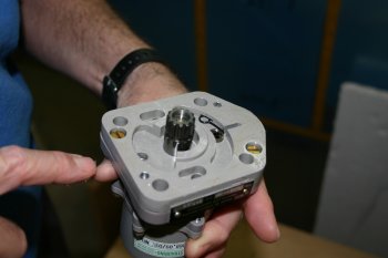
|
| | 
|
| Dad also sorted the SD-20 alternator. Same deal, grease, EZ-turn and mount. | 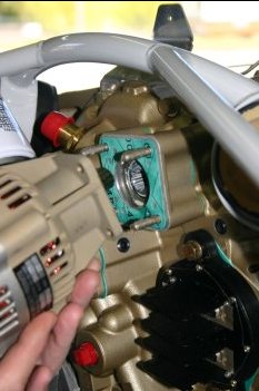
|
| However - if you have a Tach drive - you need to cap / sort this BEFORE you put the SD-20 on! Tach drive cover part number - Lycoming 62732. | 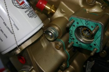
|
| Dad continued with the oil fittings. This is the oil cooler return line going back into the engine. The straight union is not going to work, either a 45 degree or a 90 degree elbow is going to be required, this is due to the oil filter having the angle adapter (which is a good thing). Another thing to add to the shopping list. | 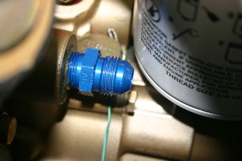
|
|
| Dad sorted some of the oil fittings and continued with a 'dummy' firewall which will hopefully allow us to experiment with the locations of the ECUs / Battery boxes / other components and get a combination that works. Removing / installing the engine back on to the fuselage is really simple and this system looks like it is going to work well. | 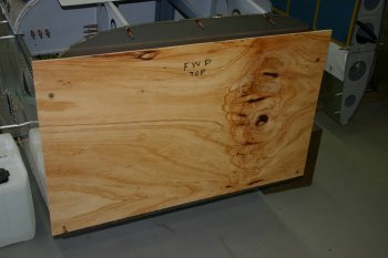
|
| Finished the day getting very confused with regard to the exhaust mounts. If you think the baffles are drawn by a 5 year old, the exhaust mount instructions are by the younger sibling! They are awful and don't provide much useful information. Also the websites seem to struggle to provide the 'location' type information. I'll do some more research and I'll get it sorted, but I don't really know what I'm aiming for at the moment. | 
|
|
| I then went back to the exhaust mounts for a little while, more thought / experimentation. More confusion, I think this is roughly right but I've asked for some guidance via email. It still seems a little 'strange' to me. | 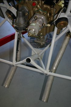
|
|
| Then it was back to the exhuast mounts. More frustration but this is the best I can currently come up with. Multiple angles to try and help anybody else in the future. | 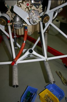
|
| The sump mounts use different locations, the LHS is further aft, the RHS is the foremost sump nut. This provide two reasonably striaght lines for the vertical supports | 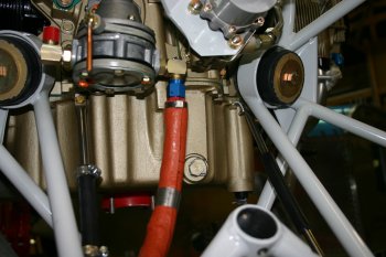
|
| The span support goes through the 'A' gear weldment and just infront of the engine mount bolts. I'll confirm this is a suitable solution once I get the engine back on the fuselage and present up the lower cowl. | 
|
|
| To finish with, I remounted the engine frame. Nothing too hard, just working around the bolts and tightening everything slowly. | 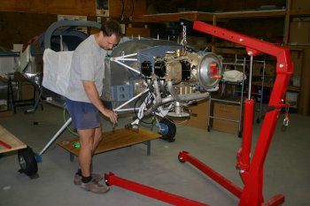
|
|
| Back with real work - we pulled the engine and frame back off the fuselage, lots more thought also completed for the push/pull controll cables - I think we have a plan..... | 
|
|
| | 
|
|
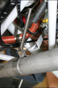
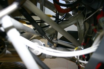
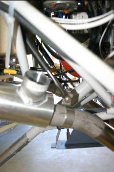
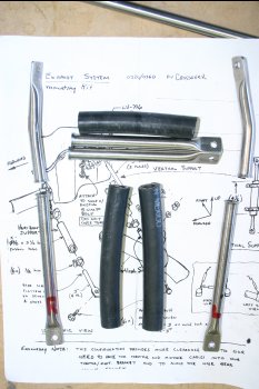
| I then went back to hitting my head against the wall known as the exhaust supports. This is a different 'non-intuitive' option - outboard facing ears, this helps provide better clearance in the forward wide of the lower engine mounts. I wish there were some decent instructions for the cross-over exhausts w/ nose gear mounts.... | 
|
| This is a close up - not sure. | 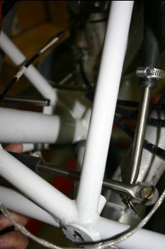
|
| This is a third option, slightly further forward on the exhaust - the problem is then multiple bends / tweaks are going to be needed - no simple solution. | 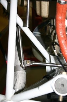
|
|
| | 
|
|
| Finished up some tieing and then remounted the engine. This also allows Dad to sort some of the alternator lead lengths / termination. | 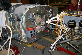
|
|
| | 
|
| | 
|
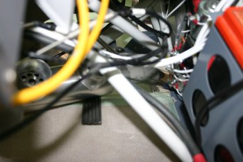
| | 
|
| | 
|
|
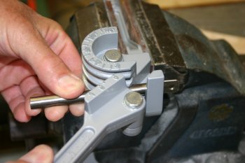
| | 
|
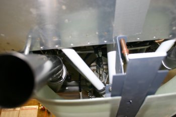
| | 
|
| | 
|
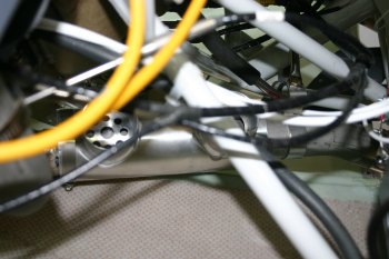
| | 
|
| | 
|
| | 
|
| | 
|
|
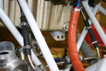
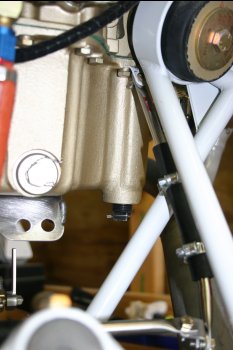
| Cover plate mounted up - the extra space works well. | 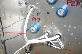
|
| | 
|
| | 
|
| | 
|
| | 
|
| | 
|
| | 
|
| | 
|
| | 
|
| | 
|
| Installed the oil restrictor fitting ready for positioning the firewall mounted manifold. | 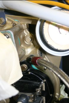
|
| I replaced the VANs supplied oil fittings with new steel elbows. These are really tight, but the standard oil lines plus two 90 degree elbows in the oil cooler seems to work OK. | 
|
|
| | 
|
| | 
|
|
| Remounted the engine frame - probably last test fit. Various things to check / work out, FADEC harness locations, push / pull cable routings, SCAT tubes etc. | 
|
|
| To finish the day I got the prop back out, mounted up the spinner backing plate. | 
|
| And went through the half turn at a time, for 6 bolts... slow but not hard. | 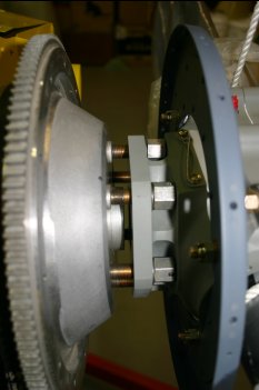
|
|
| Dad sorted the quick drain oil plug - has a nice positive lock. | 
|
|
| Then engine off - hopefully for the last time - various bits of tidying and prep. We are waiting on an order from VANs for a fuel line and other parts, but some light seems to be coming at the end of the tunnel. | 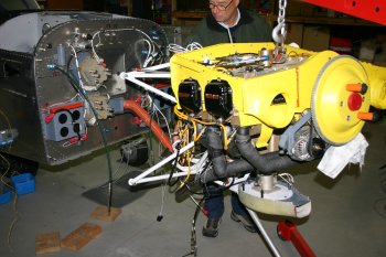
|


