


 |
 |
 |
| Home | Research | Delivery | Empennage | Wings | Fuselage | Finish | Engine | Electrical | GRTDecode | Previous|Next|Latest |
| Wings | Left Wing | Right Wing | |
Wings | |
Sat 17 January 2004 | |
| We cleaned and cleared the garage to create some more space to unpack the wings. |  |
| The QB wings are well advanced out of the box with relatively little to do to complete them. Today really it was just an inspection and understanding of what we have got. The rest of the afternoon we ended up chatting about which parts we should do next and how we want to mount the wings for storage. I also did quite a bit of reading and research which exhausted the rest of the day. |  |
Sun 18 January 2004 | |
| We spent most of the day constructing the wing cradle. The initial plan was to construct as per VANs plans with a solid end guide. However cutting and fitting the wings leading edge with enough clearance for padding was proving difficult. |  |
| Therefore we went to plan B and used the wing tips as a guide for the leading edge. This allowed the bottom support to be enlarged and we changed the support structure to use web straps |  |
| The completed wing stands. The spar is supported at the far end and the leading edge of the second rib is supported at the other. The web strap provide good even support for the aerofoil edge. |  |
| The finished wing cradle, simple but effective. Took significantly longer than we expected. |  |
Tue 20 January 2004 | |
| Whilst I was waiting for assistance for moving wings etc I cleaned up the aileron and flap mounting brackets. Yet another case of completing a piece of preparation so that when we need the part it is ready to go. |  |
| Next up I started sorting the aileron bell crank sub assemblies. These transfers the left/right movement of the stick to changing the angle of the aileron in the wing. Spent a bit of time finding all the parts in the various brown paper bags. (Hint: The brass bushing are in the large bag with all the close tolerance spar bolts.) |  |
| The brass bushing need to be opened up to 1/4" for the bolts. We used a reamer in the pillar drill which worked fine. |  |
| I then moved on to the smaller push rods. These have to be crossed drilled for two large AD4 rivets. I started with a pilot. |  |
| And then moved up to a #30 and then re-drilled with the threaded plug. All the drilling for a single hole was done with out moving the drill configuration. |  |
| Then cut the tube to the correct length with the powered hacksaw which results in a really clean square cut. |  |
| And finally repeat the process for the other end. Finish by deburring and then add it to the pile for priming (the internals need to be primed, the outside is powder coated by VANs). |  |
Thu 22 January 2004 | |
| Today I focused on the push rods. This is a V block gig that helps centre the tubular stock with the drill. |  |
| To start with I did the two main wing rods. Cut them to length on the powered hack saw, and then processed them the same as the elevator rods. |  |
| Also did some cleanup, deburring and smoothing of the wing brace supports and a couple of other pre-punched items that weren't already done. Not a bad day, but still moving fairly slowly. |  |
Thu 29 January 2004 | |
| I then started on the wing braces. These supports run along the trailing edge of the wings and provide additional strength to the flap and aileron mountings. Some trimming is needed although I got a nice surprise when I found most of the edge cleanup work had been done previously. |  |
| Assembled (with cleco's) the aileron attach brackets. Needed some additional clean up of the angle sections. |  |
| This shows the interference between the inboard aileron mount and a rivet on the upper skin of the existing QB wing. The sanding wheel soon fixed it and a file and scotchbrite finished it properly. |  |
| Then it is a dis-assemble, debur all the holes, smooth and finish. Then I returned the braces and aileron mounts to the wings for cleco'ing so we had the wing trailing edge structure all together. |  |
Fri 30 January 2004 | |
| I started the day match drilling the #30 holes for the attach brackets. Then the normal deburring and finishing of the edges. |  |
| All the aileron attach brackets are powder coated by the factory which means the pre-drilled holes for AN3 bolts are no longer big enough. A simple run through with a #12 drill does the job for the main pivot joints and a #30 for the match drilling into the aileron. |  |
| One of the challenges with the QB aileron is the third bolt on the inboard end should (as per plans) go into a platenut just inside this little mouse hole. The drawing call out is for AD3 solid rivets, but I'm completely baffled how you can set a rivet in this space. The smallest no hole yoke is still far too big and bucking looks impossible. I sent a query to the SoCAL list and the general views seem split 50/50 on 'just use a normal nylock or use cherry max rivets to hold the platenut'. The strength comes from the bolt, the rivet just stop the 'nut' rotating in the confined area. Not sure yet, I'll sleep on it..... |  |
| In the end I decided to go with a long #30 drill to match drilling the brackets to the aileron and then separate drillings for the #12. The powder coated parts I did in the pillar drill. |  |
| I also did the bell cranks whilst I was setup for the #12 drill (AN3 bolt size). |  |
Wed 04 February 2004 | |
| Next up was the aileron mount brackets. What I hadn't worked out was some of the rivet should be AN426's (countersunk) so I ended up having to drill after priming. |  |
| The brackets cleco'd ready for riveting (the rivets are top left of the drawing). |  |
| The riveting needed the longeron yoke to get the maximum travel for the AD4-11 length rivets. |  |
| The finished brackets ready for the wing trailing edge. |  |
Mon 09 February 2004 | |
| The aileron mounts all sorted. By the end we had the bucking system under control and feel a little more comfortable with it, more practice needed. |  |
| We then baked them in Central Otago sun mark "max". Seemed to all workout OK. |  |
Wed 11 February 2004 | |
| The wing surface were also scuffed, etched and alodined. The various parts will be primed and baked by the guys tomorrow. Hopefully we will pick them all up on Friday. |  |
Fri 13 February 2004 | |
| Then we went up the roads to the professionals to collect the sprayed parts. |  |
Thu 19 February 2004 | |
| I was on my own for the majority of the day so I worked through assembly of the wing braces. |  |
| Both lines of rivets for the aileron braces are easy to get to with the squeezer. |  |
| The flap braces can also be squeezed for the skin side, but with the quickbuild wing the call out for the spar rivet line is for cherry max and blind rivets. This seems fine for areas where access is restricted but for some of the rivets a simple squeezer can be used. Therefore I decided to only use the blind rivets where absolutely necessary. | 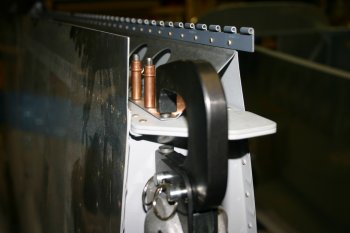 |
| The cherry max rivets are very 'clever' blind rivets with two separate 'breaks' and are used to replace solid rivets in structural locations. |  |
| The finished product doesn't look as good as a solid rivet but it is functional. If I was doing it again, I would probably buck these three rivets. |  |
| I then went down the reset of the flap brace blind rivets, although the mid point and outboard locations were done with solid rivets. | 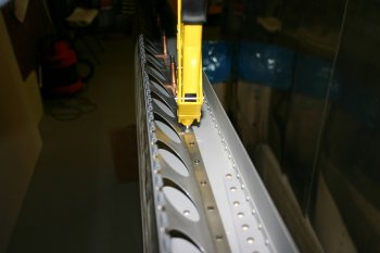 |
Mon 01 March 2004 | |
| A tube rack was also fabricated to assist with handling and spraying. We will probably etch the inside and out, then prime the internals by sloshing primer up and down and then spray the exterior. Early finish today, Dad was out for the evening and completed a significant chunk of a steel frame for a new work bench. |  |
Thu 04 March 2004 | |
| I then tried to complete the aileron wing push rods. This was all a bit of a disaster. The 470- AD4-12 kept 'bending' over and I ended up drilling out most of the attempts. I tried the back riveting plate with the rivet gun, the squeezer, hand held bucking plus rivet gun - all with very limited / no success. I think probably the back riveting plate is the best option, but the internals of the plug has no support for the rivet so I struggle to see how it can be driven straight. I also wonder why pop rivets aren't used here like the rest of the push rods....... |  |
Sat 06 March 2004 | |
| To finish the day I went back to the wing aileron push rods. After a few suggestions from various sources (thank you for the emails) I tried some different options. The most successful of which was using the C frame. I used the AN470 rivet set in the lower position with the flush bar coupled with the back riveting set on the rivet gun. The output was better and more consistent rivets however I'm still not particularly comfortable with the results. One of the newer options that VANs has recently detailed is welding the parts together. With all steel components and the lack of space / structure to rivet I like the idea of welding. No decision needed right now, but something to add to the list to think about. Early finish write up and social activities with the UK visitors. |  |
Sun 07 March 2004 | |
| I tried again with the C-Frame to rivet the other wing aileron push rod. Looks OK from the plan view. |  |
| But the side view shows how much the rivet has bent over. Conclusion, we will be ordering some additional 1/2" steel tube and getting the ends welded. |  |
Mon 08 March 2004 | |
| The aileron push rods need a couple more spacer. Normal drill cut and sand. |  |
Sun 04 April 2004 | |
 | |
 | |
 | |
 | |
 | |
Fri 03 December 2004 | |
| Nice simple job to start with, trimming the wing rear spar. Previously I hadn't twigged this needed to be completed but before the wings were presented back up to the fuse this needed to be done. As it is a fairly important cut (minimum edge distances for the joint) we did it the old fashioned way - by hand. |  |
| Then after much debate, emails and thought, we elected to use a reamer on the 'laminated' plates on the spar so the close tolerance bolts will fit.
The factory basically just say use a hammer to 'knock' the bolt in, however even without the spar in place we couldn't get smaller shop bolts through the rear sections. The various options seem to be 'scraping' the hole out or (as we have done) use a brand new, sharp accurate reamer of the right size to finish the holes. It is probably only a couple of thousands of an inch too small but if we had gone down the hammer with a 'light' tap, it would have had to be a club hammer and the bolts would have been one time 'nails'. It is also important for us that the wings can go on and off as some maintenance may need to be away from the airfield. A difficult call (whether to ream), but we used it sparingly, after a lot of testing (and close tolerance bolts) and then very carefully. Don't follow me - call the factory! |  |
| We then presented the wings up to the fuse and got to see the first real alignment. |  |
| We had some problems getting the tongue in the slot for the rear spar, but a little persuasion and it all slipped in neatly. |  |
| We also got all 4 shop bolts in and the wing was getting very 'tight'. No movement at all and when the close tolerance bolts are use it will be rock solid. |  |
Sat 04 December 2004 | |
| Then I knocked up a couple of wing support stands. Nothing clever, a couple of 2 1/4" flat bit hole in a piece of timber. |  |
| A protective rubber top and onto an car axle stand. Does the job nicely and help to provide 'roll' stability / safety whilst the wings are attached. |  |
| Then it was onto levelling the fuselage across its length and width. |  |
| One side need to be lifted slight, a hydraulic car jack took the load whilst packing was found. |  |
| Check and double check. |  |
| Then we had a look at the wing angle of incidence. Generally it is looking good but needs to come up a little at the rear. Early finish, social evening. |  |
Sun 05 December 2004 | |
| One of the key rigging measurements is the wing sweep - or lack thereof. The RV 7 wings are completely straight - or should be. We stretched a reference line across the floor and then use a plumb bob to align the outmost and inboard leading edges. Generally both wings were pretty good - about 1/4" difference along the length, but both were slight swept forward. |  |
| Part of the reason for the problem was the first rivet above the rear spar attach point. The AN470 (domed head) rivet interferes with the wing spar. |  |
| The solution? Either remove material off the spar or remove and replace the rivet with a AN426 (counter sunk) rivet. I decided to go for the later. | 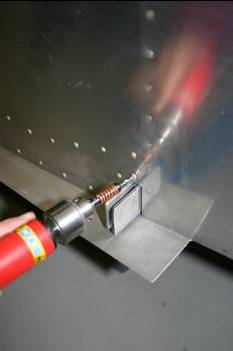 |
| Even with the rivet modification, a little filing on the spar was needed to assist with the various rigging requirements and mounting processes. |  |
Mon 06 December 2004 | |
| After some of the frustration from yesterday, I started this morning with some 'therapy'. Edge smoothing and preparation for some parts I will need in the future. I've found on a number of occasions that doing the basic processes allows time to relax a bit and step back from the problems at hand whilst still progressing the overall project forward as it has to be completed at some point anyway. It is also really good to pick up a 'new' part and find it already prepared and that in turn accelerates the assembly process. |  |
| Dad mean time was still struggling with the lower 1/4" main spar bolts. Again the plate alignment was out and the shop bolts weren't even starting to go through. More careful reamer work, slowly and only where absolutely needed. |  |
| I then started on the front wing / fuel tank attach bracket. This first required drilling out some rivets (which shouldn't have been set) just behind the leading edge of the wing. |  |
| The edge distances for the shims and strengthener inside the fuselage are very tight and I ended up making the two sheet shims slightly longer to easy the upper edge clearance. |  |
| The other issue we have is the QuickBuild guys have fluted and dimpled the skin / bulkhead which makes getting the internal stiffener / shims to lay flat very difficult. |  |
| Then it was on to parts fabrication. Normal drill - first understand the drawings, then make a couple of 'proto-types'. The 3rd and 4th attempts are fine....... The key here was the strange angles and exact lengths of the AL angle. It does work and the edge distances are OK, but very tight. |  |
| Dad also super-glued the washer / spacer to the right location for the gear leg weldment. Otherwise this is a real XXXX to get inserted and lined up. |  |
| The final part of the day I sorted the match drilling of the bracket / shims and skin. Both sides are now ready to be opened up for AN3 bolts and match drilled for the external tank bracket. |  |
Tue 07 December 2004 | |
| I continued first thing with the wing tank attach brackets. No problems, just careful drilling. |  |
| Then we moved onto the rear wing spar. The project has a number (half a dozen ish) of major milestones / events, things like Rudder trailing edge, Wing spar drilling, Canopy cut, Engine mounting, Engine first start, First flight. Well today was number two on that list - Wing spar drilling. As we have already had the wing on we knew where we wanted the hole to go and the edge distances needed to be. Therefore we (carefully) marked out the fuselage tongue and I center drilled it. |  |
| Then using a long #30 drill I made a pilot hole through the rear plate. |  |
| Next it was the usual fun and games mounting the wings. This is when having two people working on the project makes life SO much simpler. |  |
| After using shop bolts for the initial alignment a pair of 'sacrificial' close tolerance bolts were put in on both sides to lock the main spar position. |  |
| Then it is lots of measuring, adjusting and tweaking the two wings to get the sweep and incidence just right. They sweep is setup via the plumb bob and reference line between the inboard and out board ends of both wings. The should all be in a single line. |  |
| The wings should be for/aft the same amount both sides. We did this from the out most rivet on the main spar to a central line just under where the vertical stabiliser attaches. |  |
| Then the incidence is checked with a block and 'spirit level'. This is when the use of the smart level is fantastic. It is calibrated in .1 of a degree. Out of the box both the QB wings are within .1 inboard to out bound and they were about .1 (LHS) and .2 (RHS) for the right incidence angle. Incredible how all the CNC punched parts / QB components (from two different countries) come together that accurately. |  |
| After multiple checks and re-checks it is then the big drill. Starting with a #30 and working up to a 5/16" hole. Space is quite limited which makes it harder and again two people helps with the alignment of the hole. |  |
| Once both of the rear spars were done, I started looking at the front fuel attach bracket. Looks OK although we won't need much of a bend in the bracket. I need to revisit tomorrow. |  |
| So there we go - wings drilled and mounted on the airframe.
Big day psychologically but relatively simple, just take our time and work slowly through the information.
I'm sure we are being over cautious at times but to honest - I don't care that much, we are never going to be the 'fastest to complete'.
I would rather understand and do it slowly than run at this point and make mistakes. "Wings on" is a pre-requisite for several other things so hopefully I can start focusing on and make progress on some of these now whilst Dad is going to continue with the gear weldments. |  |
Wed 08 December 2004 | |
| I continued first thing with the tank attach brackets, a small crease in the steel is needed to get everything to sit nicely. Once bolted to the fuse I drew round the bracket onto the wing ready for marking and drilling when we next have the wing off. |  |
| Next was the wing root trim. Nothing to complex but I wanted to understand the layout of the holes and mark up the wing ready for the appropriate rivets to be drilled out and replaced with nutplates. |  |
| The leading edge needed some persuasion to form properly but it came out ok. |  |
Fri 10 December 2004 | |
| De-rigged the flap / ailerons ready for the wings to come off tomorrow. |  |
Sat 11 December 2004 | |
| However once we managed to separate the wings the additional space and access was welcomed. |  |
| The pre-punched parts here are a bit of a mixed blessing. The best solution we came up with was to use the underside screw and then wrap round to the upper tank screw. Then everything can be adjusted to get an even distance from the edges of the cover / wing. Then it is the normal cleco, drill, debur, dimple routine. |  |
Mon 13 December 2004 | |
| Now todays question: We need to get multiple cables, air lines etc from one end of the wings to the other. My intention is to use conduit, however it requires 13/16" hole the length of the wing, with the inboard lower skin already riveted. I see a number of options but not sure of the best, a question to the lists is going out tonight...... |  |
Tue 14 December 2004 | |
| Today I was on my own, so I looked at the nav / strobe lights with the wing tips |  |
| The base of the Whelen lights require something to screw into. One option is to put the nutplates directly in the fibre glass. However we decided a 'AL washer' would be a better solution. I knocked up a CAD diagram of what was needed and started with a couple of pieces of 032 AL sheet |  |
| The only method I had to create 1 5/16" was with a fly cutter. Worked OK on the AL, but not good for the fibre glass tips. |  |
| The rest of the shaping was OK. |  |
| I gave in and went a purchased a new hole saw (1 3/8") which made the right size main hole in the fibreglass tips. |  |
| To finish the shaping I used a rotary burr - this was all a bit new as I haven't worked on glass components before. It was actually easier than I thought. |  |
| Then the problems occurred - the plate wasn't really big enough for the nutplate mounts. I could of used one legged nutplates (but didn't have any) and decided the easier option was just to re-make the plate bigger. |  |
| All finished with nutplates installed ready to go. I also started looking at the tip plexi-glass covers which is tomorrows activity I think. |  |
Wed 15 December 2004 | |
| I spent the day with the wing tips. The first area was the lens. First step is to split the lens in two. |  |
| The angle die grinder worked well. |  |
| Then it was a trim along the bottom and then a simple trim at the back. |  |
| Then it was just a slow iterative process, of mark up, trim and re-fit. |  |
| The lens can move forward / back and finding the 'right' location is a bit tricky. I ended up sorting the front / side and then the top / bottom points. |  |
 | |
| Then it was more iterative work, this time with the sander - all came together OK, just slow. |  |
| Getting there. |  |
| Finished product, only the fixing options needed. I will probably go with a single screw top / bottom, but it may be better with a couple to reduce the stress in the corner of the lens. |  |
| Good news - one completed, next job the other side. |  |
| The second time was quicker, as I had some idea of what I was aiming at. |  |
| Same process, all came together eventually |  |
| Then I went onto fitting the tip to the wing. |  |
| First thing was to rebate the trailing edge, the iterative burr works on the fibre glass. |  |
 | |
| Then I realised that the step for the wing skin needed 'cleaning up'. |  |
 | |
| And the flange needs to be trimmed dramatically. I ended using the rasp file, which worked well if a little slow. |  |
| I manage to complete trimming of the LHS tip, tomorrow hopefully mounting it. |  |
Thu 16 December 2004 | |
| I continued with the LHS wing tip mounting. Firstly more trimming was needed. |  |
| I worked up from the bottom (leading edge of the wing) back, top first, then the underside. |  |
| Dad supported the tip surface from inside |  |
| All mounted with #40s. |  |
| I finished with the simple job of opening up the holes to #30s. The finished results looks ok although the LE join between the metal skin and 'glass tip will need some filler / work. |  |
Fri 17 December 2004 | |
| I started with more triming of the RHS wing tip. |  |
| Sorted the upper and lower brace strips for the LHS tip. Only drilled to #30 at this point, we are looking at another Avery tool order which will include some more 'black' clecos. Then the #28s (or whatever is needed for a #6 screw) can be match drilled on the wing, tip and brace. |  |
| Next up was the RHS tip drilling, #40 first then #30s. |  |
| The final step was the top and bottom brace strips for the RHS tip |  |
Fri 24 December 2004 | |
| Then we started tidying for Christmas. A full sweep-out and clean. |  |
| and the wings both back on. |  |
| I did the match drilling for the lower wing skin nutplates. |  |
Sun 26 December 2004 | |
| Whilst the wings were on, I put the wing fairings back on and marked the 3/16" line for later trimming. The lower aft most nutplate location is going to be real difficult but I'm waiting until I have more space under the fuse (when the undercarriage is on) before sorting it. |  |
Tue 28 December 2004 | |
| I then went back to the wing tips. The inner metal strips for the nutplates needed to be final match drilled to the tips and wing skins and opened up for #6 screws. The problem is holding the strips to the fibreglass tips whilst everything is put into place. The easiest solution that I could think of was gaffer tape, a bit patchy but did enough to be able to complete the clecoing. |  |
| Once everything was cleco'd together the nav light holes at the front of the tips provided a sight line to check the metal strips. |  |
| Then simple drilling to #28's, just take it slowly so the 'tension' of the strip does the pressure against the drill bit, otherwise you can pop-off the cleco's (and bend the metal strip - don't ask me how I know) |  |
| Then it is start the normal process, in this case 76 nutplates, with 2 rivets each. That is a lot of holes to drill, debur etc..... |  |
| Normal edge preparations, then dimpling and prep. Didn't complete the riveting today. | 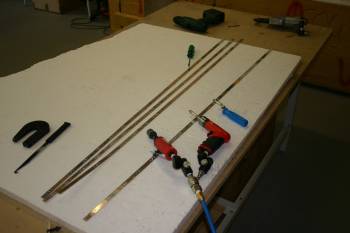 |
Fri 31 December 2004 | |
 | |
 | |
Thu 13 January 2005 | |
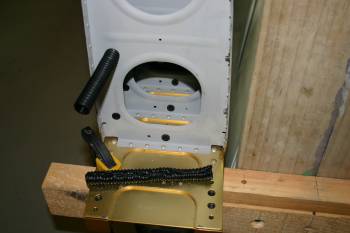
| Then we moved to wings and conduit locations. Dad made a template jig and we used a long #30 drill. |  |
| Then opened to 3/4" with the uni-bit. |  |
| The long 12" reach option as needed. |  |
Fri 14 January 2005 | |
 | |
 | |
 | |
 | |
 | |
 | |
 | |
 | |
 | |
Sat 15 January 2005 | |
 | |
 | |
 | |
Thu 05 January 2006 | |
| To finish the afternoon I started back with the wing tips. The trailing edge rib is going to be a challenge and will need the ailerons mounted to get the alignement and I think having the screw locations bonded to the tips is also a pre-requisite. |  |
Fri 06 January 2006 | |
| Continuing with other things, I deburred and dimpled the wing skins for the tips. |  |
| If you are building - don't follow my lead here - the 'correct' method for the nutplates on the wing tips is to have the rivet going through the tip along with the backing strip. I've already riveted the nutplates to the backing strip - therefore I'm just going to use resin / silica flox as a glue. The strength comes from the spreading of the load so I'm not too concerned. |  |
| So a large-ish batch of resin work, scuffed all the parts and cleaned with acetone. |  |
| With the first batch of resin the mixture seemed more 'stringy' than usual - not sure why, so I focused on the wing tips rather than other areas. Basically a thin layer and then fully cleco'd the #6 screw locations. |  |
| Continuing with the other side of the wing tips I finished the LHS completely, but still have the lower RHS strip to do. With that only being a 'half-batch' I decided to wait. Tomorrow hopefully I can complete that and do some more micro-balloons for the rudder tips. |  |
Sat 07 January 2006 | |
| Starting with the wing tips today - the flox along didn't seem that strong so I added 4 rivets along each length. |  |
| Continuing with the resin work, a half batch for silica and the wing tips, the second half batch for one side of the lower rudder tip. |  |
Fri 13 January 2006 | |
| I continued with the wing tips - these need trimming for clearance with the ailerons. The plans state 1/4" but that leaves about a 1/16" step between the wing skin line and the designed gap. |  |
| After a bit of thought, we elected to make the alignment simple and continue the wing skin line aft on the tips. This will also provide a little more flexibility in side to side mounting of the ailerons if needed. |  |
| Clamping the work for the die grinder was simple but the use of the AL rib helped keep everything firm. RHS tip done, LHS still to go. |  |
Mon 16 January 2006 | |
| First up I completed the wing tips work, we will need the wings and ailerons mounted to move on further. |  |
Sat 18 March 2006 | |
| Also sorted the forward wing tank brackets. The bolts are a PITA to hold on the inner location, also note the direction of the nuts / bolts - don't ask me how I know....... |  |
Fri 24 March 2006 | |
 | |
 | |
 | |
Fri 22 December 2006 | |
| Today was getting the wings back on (at least with shop bolts). |  |
| The forward tank attaches were a bit of problem but were sorted. At this point we have just laid the main wiring runs through the aft rib holes. |  |
| One thing I spotted was the aft wing / fuselage intersection didn't look right. After some more digging I realised I've missed a nutplate location on both sides - Opps. |  |
| Both wings back on - starting to look like a plane! |  |
| Also got the ailerons mounted, however push rod lengths look very marginal. |  |
Sun 24 December 2006 | |
| I wanted to play with some of the rigging and alignment components. I know the wing tips are going to need work, but wanted to get the flap / ailerons sorted first. The use of tight cord worked well for the trailing edge alignment. |  |
 | |
| This could then be worked back to the flap position and I spent more time getting push rods the right length. The main wing / aileron push rods seem very marginal. The length specified by VANs is in the 'mid position' and means adjustment is limited. My advice for any other builders - a 1/4" could be safely added to the wing tubes and will make life easier in long run. |  |
Thu 28 December 2006 | |
 | |
Sun 31 December 2006 | |
 | |
 | |
 | |
Mon 01 January 2007 | |
 | |
Tue 27 February 2007 | |
| With the required bits done - at least for the moment - with the wings on, we started prep'ing the removal. One area still to be sorted is the flap hinge pin retention and the trailing edge of the wing root needed an additional #8 / nutplate - I missed this previously as it isn't in a rivet location.. |  |
| A photo of the aileron stops - installed - the idea was copied from Mickey. |  |
| Wings gone again - seems like we are going backwards sometimes, engine off, wings off, panel out etc.... |  |
Mon 03 September 2007 | |
| Nutplate mounted with "AD3" pop rivets on the alerions - fiddly.... |  |
Sun 16 September 2007 | |
| Also knocked another item off the list - wing tip ribs rivetted in. |  |
Sun 30 September 2007 | |
| Not much done - but drilled / set the nutplates for the plexi covers on the wintip edges. I was nervorus about shooting / bucking on the fibreglass - but in the end it was fine - just took it slow. |  |
Fri 05 October 2007 | |
 | |
Sat 06 October 2007 | |
 | |
 | |
Sun 07 October 2007 | |
 | |
Mon 08 October 2007 | |
 | |
Sun 14 October 2007 | |
| More rigging and travel tests. The pushrod lengths are still marginal. |  |
Sun 18 November 2007 | |
 | |
Thu 22 November 2007 | |
 | |
| Home | Carl Morgan | Previous|Next|Latest |