Rudder |
|
| Laid out all the rudder parts and studied the drawing. Worked out three pieces had to be fabricated from stock material and the reinforcement plates are in a brown paper bag (not in the general pre-punch metals bits). | 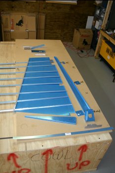
|
| These are the stiffeners that are used in the rudder. They come in 8 double length pieces that have to be 'snipped' into 16 stifferners. | 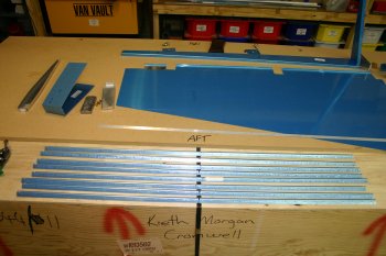
|
| This is the after photo, 9 out of the 16 have also been finished for the long tapered edge. Time for some rest. I'll finish the remaining pieces tomorrow. | 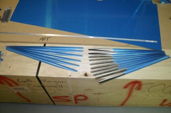
|
|
| Finished some of the stiffeners sanding and fabricated the R918 parts.
Cleco'd the internal structure together to get a good understanding of the way it all fits. Then we packed up the bits to returned to the Horizontal Stabiliser. | 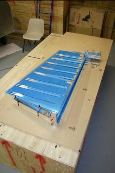
|
|
| Second task for the day was to cut the stiffeners for the rudder. Using the powered band saw seemed like a good way of cutting them to length, so I lined them up and set the machine going. However it tended to grab at the end of the cut and damaged a couple of longer stiffeners. | 
|
| Luckily it was the first batch, so I made the damaged ones shorter and cut the second batch by hand. A much better solution. After that they all had to be marked, sanded, profiled and cleco'd out on the skins. | 
|
| The cleco'd skins being match drilled to #40. All completed quite quickly. | 
|
| The rest of the day / early evening we spent working through the internal structures for the rudder, deburing, sanding, drilling etc the various components. No other work on the skins completed - that is for tomorrow, otherwise a good progress today considering a later start than normal. | 
|
|
| Cleco'd the skins to the underlying structure and match drilled all the #40's. Also sorted the counter balance weight in the top rib. A few days ago we removed 4 ounces from the VS reinforcement bar, today we add 25 ounces of lead! I know it makes sense, but still amuses me slightly. | 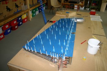
|
| The rest of the day was spent working through all the various rudder components and deburing, filing, smoothing, sanding, polishing preparing parts. Got about 70% of the way there. Tomorrow need to finish the skins and start dimpling. | 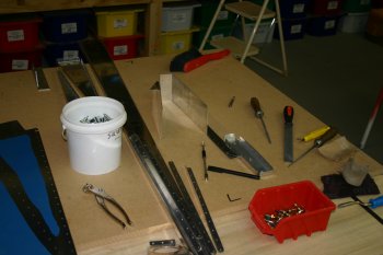
|
|
| Started the day deburing all the skin holes. As the control surface skins are very thin I did it all by hand, a single turn of the counter sink was plenty. Using the polystyrene from the shipping crates helps here to support the skin. | 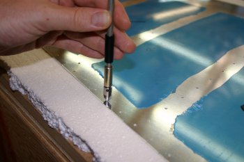
|
| Then came smoothing of the edge of the skins. This is even more delicate due to the thin skins. | 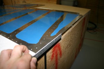
|
| After using a file to remove the pressing marks, I ran the edging tool to remove the very sharp edge. Two passes were plenty. I only smoothed the three edges excluding the trailing edge. We will do that after the rudder has been put together for the final time (and then only very lightly). | 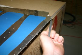
|
| Dad was meanwhile deburing and smoothing edges on all the stiffeners, these were then dimpled. | 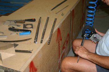
|
| We then dimpled all of the spar components of the Rudder. With the two aft most rivets of the ribs we could not fit the vice dimple or yoke based dimple dies in so we just counter sunk them. I have no idea yet how we are going to set the rivets in these locations yet..... | 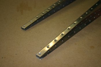
|
| The final part of the day was using the C frame dimpler. We setup some polystyrene and a piece of carpet to support the skins whilst we were dimpling. With two of us it only took about an hour to do both skins and they came out really well. | 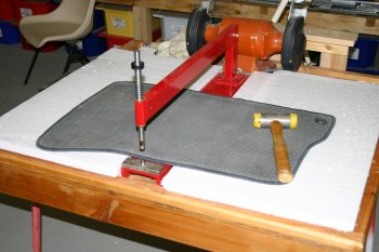
|
| Most of the rudder is now prepared. A little more dimpling may be needed tomorrow and we need to work out how to counter sink the AEX wedge on the trailing edge. | 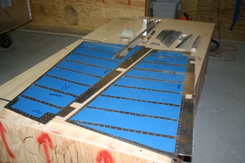
|
|
| Dimpled the trailing edge with the pneumatic squeezer. Tried to keep it fairly light and it came out OK. | 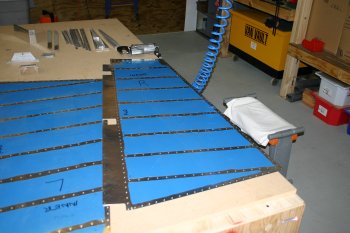
|
|
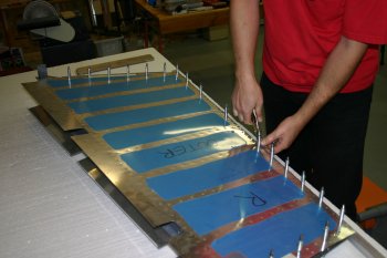
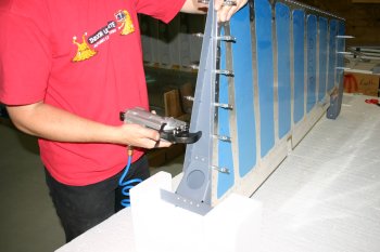
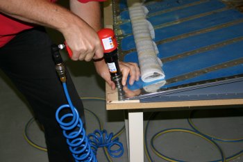
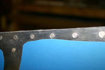
| Another day, another set of skills to learn and work out. At this stage in the project lots (most?) things are new to us. Today we started back riveting. The rudder and elevator surfaces use very thin sheet AL (0.020" - 20 thousandths of an inch) these then have stiffeners attach to them to strengthen the skin surface. To get a nice flush finish of the rivet a large steel plate is used to 'hold' the rivet flat with the skin surface. The shop head is then 'hit repeatedly' with the rivet gun to fix it in position. | 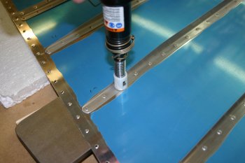
|
| Some assistance to hold the rivets in place is 'rivet tape'. Seem quite an expensive form of sticky tape, but I have to admit it seemed to work well. | 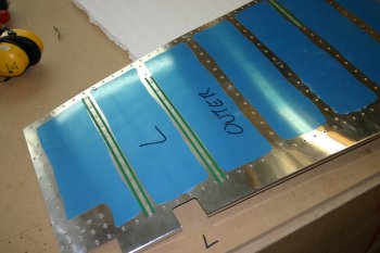
|
| I started with the L rudder skin, all fairly simple and straight forward once I got setup. I found about 40 psi for ~3/4 second seemed to work well. | 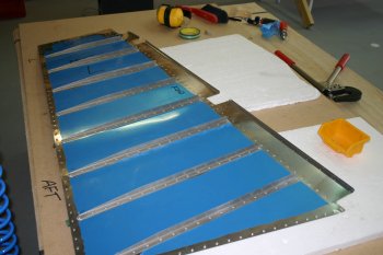
|
| Then the same deal with the right side skin of the rudder. | 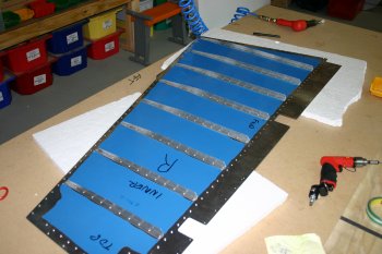
|
|
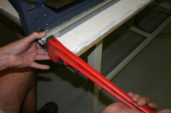
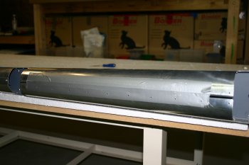
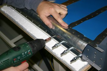
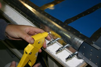
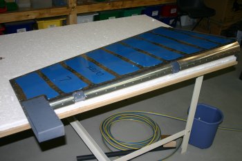
| The rudder trailing edge has a special extruded strip which is angled on both sides. This needs to be countersunk and a the construction plans talk about a piece of angle for keep the edge straight. I have to admit I'm slightly confused / lost with the instructions for the rudder riveting.
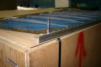
The first step seems to be to create a angle stiffener to keep the rudder straight during riveting. This is done by match drilling the skin to a piece of "spare" AL angle. We chose to use 0.125 angle as it seemed to provide a stronger, straighter edge.
| 
|
| I then used the new angle to drill pilot holes up against the edge of the work bench. | 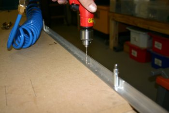
|
| Then I could cleco the AEX wedge onto the edge of the bench with no over / under hang. | 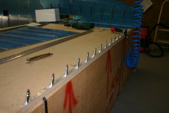
|
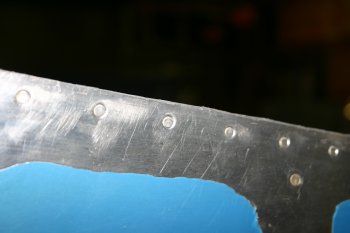
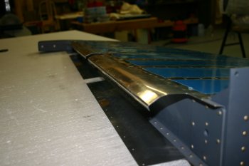
| The microstop was then used with a non-centred countersink to provide the relief for the 0.025 AD3 dimples in the trailing edge of the rudder. Both sides of the AEX have to be done. The holes didn't come out particularly smooth but are fit for purpose. | 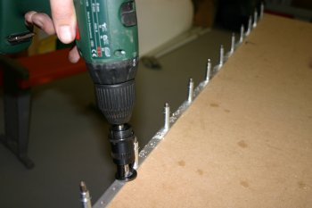
|
| The finished setup with. Now we need the pro-seal and prime the rest of the rudder parts. | 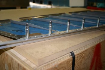
|
|
| We are still without Pro-Seal / epoxy for the trailing edges, however I realised today multiple (most) parts of the rudder can be assembled without the trailing edge being completed. | 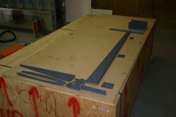
|
| The first stage is the skeleton structure. Making sure the reinforcement braces are the right side and right way round. | 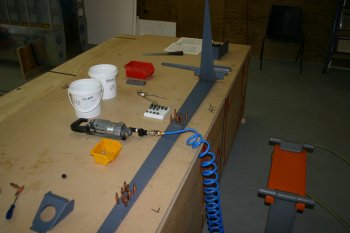
|
| Then squeezer with the longeron yoke. No big issues, plenty of space / access. | 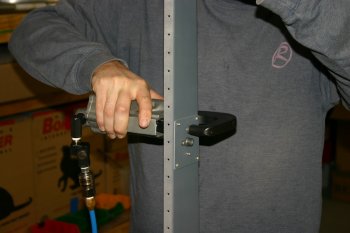
|
| A couple of the lower rivets required bucking. | 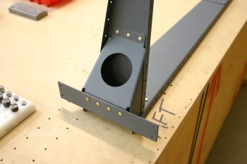
|
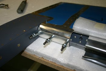
| Next up is the upper counter-weight. These had to all be bucked as the long nosed yoke wasn't long enough! | 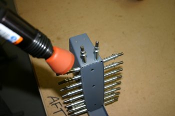
|
| The lead counter weight needed to be significantly trimmed for the rivet shop heads. | 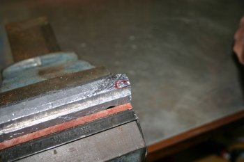
|
| After a bit of experimentation we found the rotary burr in the pillar drill worked well. | 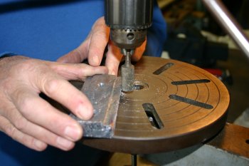
|
| The installed weight, torqued up and ready for closing up. | 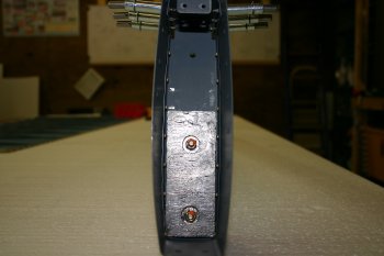
|
| We then moved onto the skins. This seems slightly counter intuitive to me, but the instructions definitely get us to do this before the AXE wedge pro-seal fun & games. So normal deal, cleco on and prep for riveting. | 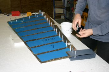
|
| The upper overlapping skin needs a slight 'bevel' which isn't that easy to apply. After dimpling it is even worse..... Another occurrence of trying something for the first time where it will show. Seems to have come out all right, we will see how the skins finish up. | 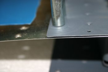
|
| Six of the internal rivets can be set using the yoke, the remaining three will have to be bucked. | 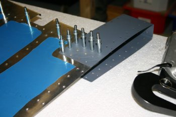
|
| Bucking in that small cavity required some 'new' bucking bar, so Dad polished up another face of an existing bar. Grinder to get the first cut and then a large scotchbrite wheel. Steel eats the scotchbrite pretty quickly. | 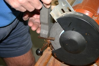
|
| We decided to mount the second skin before bucking the top. Also now is the time to remember to remove the internal blue plastic..... | 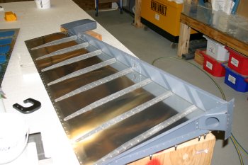
|
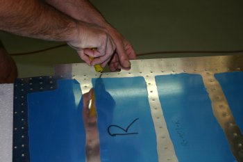
| The skins needed a bit of edge tidying, when we did them originally we were very tentative due to the thickness (or lack thereof) the sheet. Nothing serious just a few burrs on the edge that will be rolled.
.. | 
|
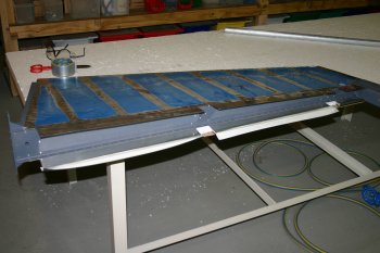
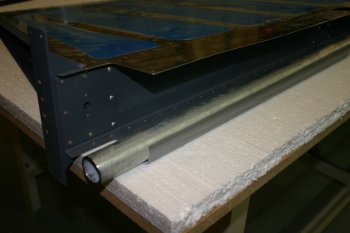
| Second skin cleco'd up plus the AXE wedge and angle support all setup (no pro-seal). We found the trailing edge needed a bit of cajoling to get everything lined up. If I was doing it again I think I would hold off the upper skins rivets until both skins are cleco'd together. | 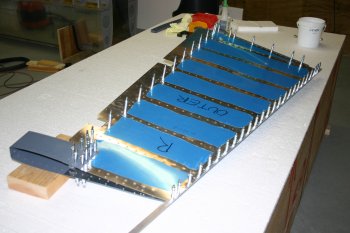
|
| I set the upper squeezed rivets on the second side and left it there for the day. Tomorrow we will start on the bucking. Just need to find some pro-seal...... | 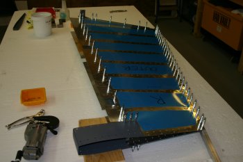
|
|
| First thing was the bucking of the upper skin rivets. This is difficult as the skin has no support and is rather flexible, so we didn't push our luck too much. | 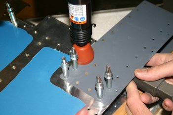
|
| Once the internal skin rivets are done, the top rib can be put in place. These can all be squeezed. | 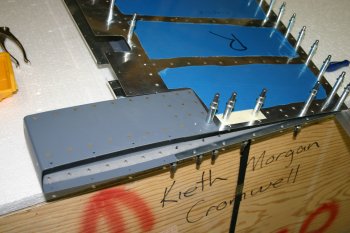
|
| Then it is the leading edge rivets on both sides, these were all set tip to bottom. The rudder was then put on one side waiting for Pro-Seal. It sounds like the NZ supplier might be able to sort something this week - we live in hope. | 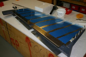
|
|
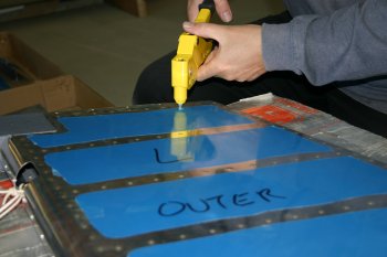
| Next up was the rudder trailing edge. Another mix of about 3 ounces worked well. Pro-Seal is a bit like sugar syrup or condensed milk, 'stringing' and very sticky. A second person on hand is very useful. | 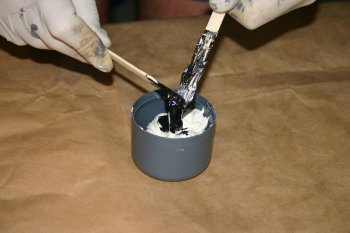
|
| I un-cleco'd the trailing edge wedge from the rudder and used acetone on the skin surfaces. | 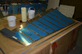
|
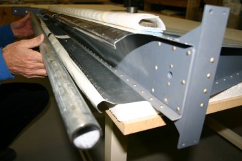
| I then held the skins apart just enough for Dad to be able to spread some Pro-Seal at the end of each of the stiffeners. We used little spacers every few ribs to hold the skins apart, otherwise the skins set together (without the wedge) and are difficult to separate again (don't ask me how I know!). | 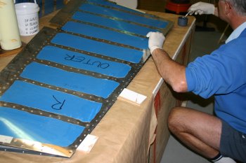
|
| Then a thin layer on both sides of the wedge. | 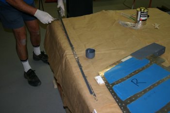
|
| This all comes together as a sticky, gooey trailing edge. | 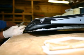
|
| You can see each of the stiffeners have pro-seal top and bottom and these meet when the skins come together. | 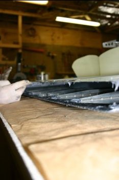
|
| I then moved up the trailing edge cleco'ing every hole. The AL angle worked well keep the surface flat and straight. | 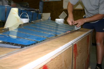
|
| Before using each cleco I dunked it in Acetone. I'm not sure if this is just going to help the pro-seal stick to the cleco or help assist being able to remove the cleco later - we will see. | 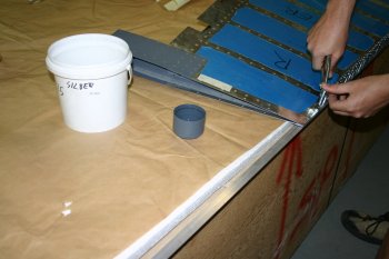
|
| The finished edge with the skins cleco'd top and bottom as well. I also ran along the edge squeezing (with a cleco clamp) the skins together. This helped compress the extra pro-seal and it oozed out of the trailing edge and reduced any gaps between the skin and wedge. | 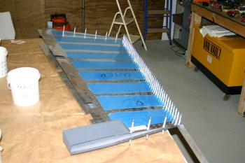
|
| The lower end. You can see how the Pro-Seal has formed a neat cushion around the stiffener. Now we have to leave the trailing edge to set before we start the riveting process. | 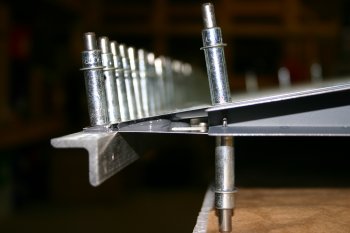
|
|
| | 
|
| | 
|
| | 
|
| | 
|
| | 
|
| | 
|
| | 
|
| | 
|
| | 
|
| | 
|
|
| | 
|
| | 
|
| | 
|
| | 
|
| | 
|
| | 
|
|
| | 
|
| | 
|
|
| | 
|
| | 
|
|
| A short day, sorted the rudder tip shaping and drilling | 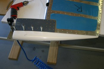
|
| Also started the bottom tip, quite a bit of trimming - but looks OK so far. | 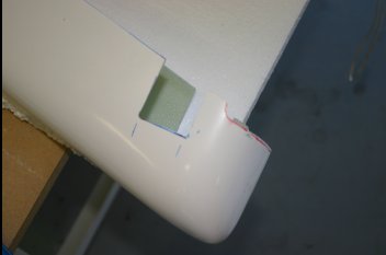
|
| Finally got it to slide on, the leading edge is still very tight - might think about warming it slightly. Haven't done any drilling yet - the step from the tip to the skin is rather noticable. | 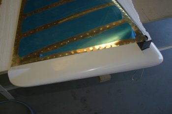
|
|
| The whole family thing was starting to get to me a bit, so I had some timeout fiddling on the project. Wanting something fairly mindless, I focused on the sanding of the rudder tips. I think all the first layup of micro-balloons have now been processed, a few pin holes but generally better than expected. The masking tape, electrical tape for edges and palm sander with 150 & 240 paper seems a good solution. | 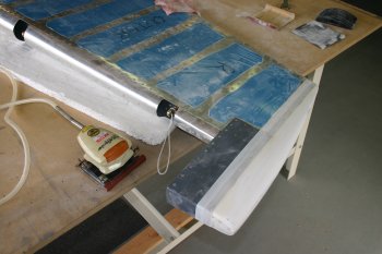
|
|
| Today got back to the project for a proper half day. Continuing with 'bits' I went back to the rear tail light. The basic problem is the two small (#4) screws / nuts are almost impossible to install. | 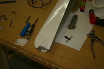
|
| The best option that we could come with was for a AL base, remove most of the fibreglass, and soldered a core of copper on the two nuts to stop them rotating. | 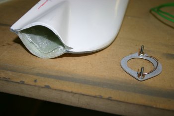
|
| I mixed up a stiff batch of silica resin and bonded the two halves together. Hopefully the boelube on the screw threads will provide a release agent. We shall see....... | 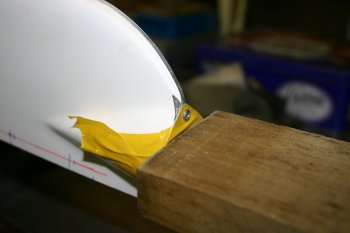
|
|
| A partial day with other commitments this afternoon. Continuing with the rudder tip / tail light - I removed the screws without a problem first thing and started trimming / tidying the semi-cured resin / silca mix. | 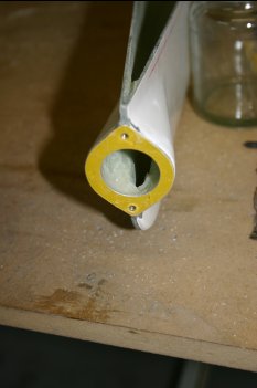
|
| Everything looked good, but I could see a crack on the lower screw location - this is where I tried removing the screw before it was set yesterday - BAD idea. I ended up removing more flox and managed to extract the cracked bit, this was then cleaned up and prep'd for more silica. | 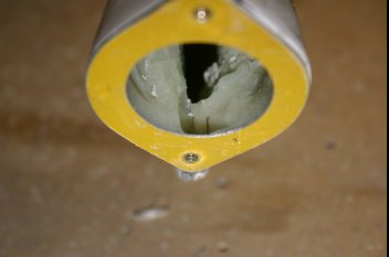
|
|
| First I cleaned up the tail light mounting, the final result I'm pleased with. | 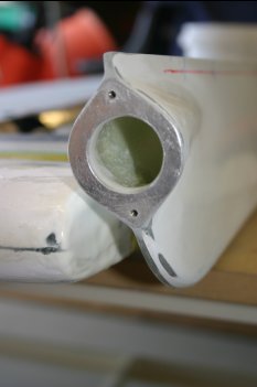
|
| Then it was lots of sanding.... slow iterative process. | 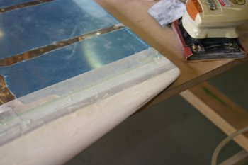
|
| With the rear light sorted I laid out the rivet patten, deburred and countersunk as needed. I also added an AD3 on the forward side of the control horn. | 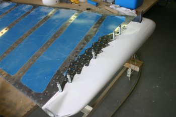
|
| Everything was openned up for CS4-4 rivets and normal misc shaping / edge clean up. | 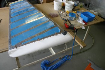
|
| Also sorted the masking - this is the technique we are using for all the fibreglass resin edges. First a 'finish-line' of green masking tape, then a wide band of normal masking tape for protection and finally a sacrifical edge of electrical tape. After laying up a resin / filler film I sand back with 80-150 grit to the electrical tape, then 150 sometimes remove the electrical tape, but then re-apply a new replacement. This means the green masking tape will only be used on the final edge / feathering. | 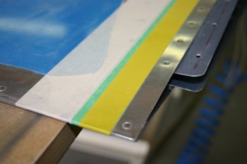
|
|
| With the next batch being a more normal mixture, I started with the rudder lower tip. | 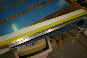
|
| We found having the rudder vertical and sliding on the tip from above worked well. Then laying on its side for the pop-rivetting. | 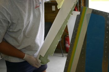
|
|
| Then more fibreglassing, second side of the rudder lower tip with micro-balloons and also re-fixed the nav light spreader that came off yesterday. | 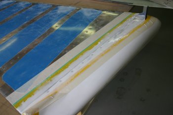
|
|
| For most of the afternoon, I continued with the sanding of the rudder tip. Starting with 100 grit paper on the palm sander, | 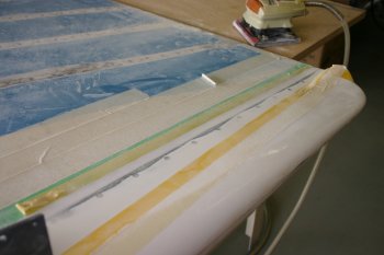
|
| then removing the protective electrical tape and going down to 150 grit. This provided a nice blended edge to the micro-balloon filler. | 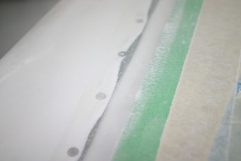
|
|
| Before de-rigging the HS, we put the rudder on to check the VOR antenna clearance - no problems. | 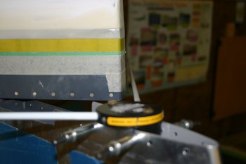
|
| and the rudder stops - although I made them slightly oversize, the RHS is still rather tight. The slight left bias of the VS seems to be enough to reduce the clearance so I'll need to sort a new one at some point. | 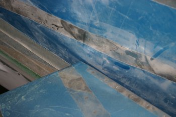
|
|
| Remounted the rudder, tweaked the ball joints slightly (an extra half turn in) which seems to help with the rudder stops. | 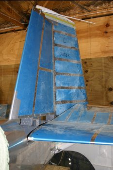
|
|
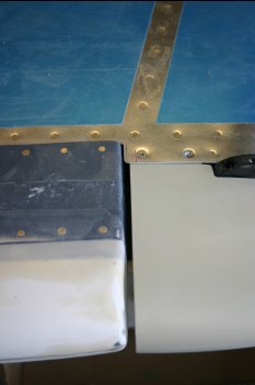
| Dad put the 5/32" pop-rivets in the forward upper locations of the VS - something that has just been on the list for a while. | 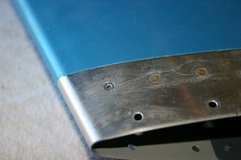
|
|
| | 
|
| | 
|
|
| After more trimming, then pasted up a resin layer on the rudder fairing cable guide. | 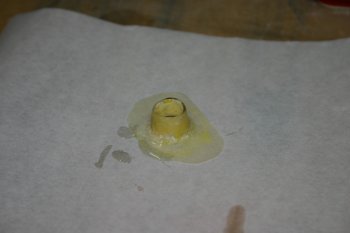
|
| More scuffing and then fibreglass work - sorry didn't get an after photo. | 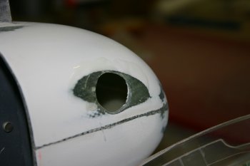
|
|
| And trimmed / cleaned up the rudder fairing work from yesterday. | 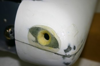
|
| After the edges were blended - now ready for a 2oz layer over the whole lot during the next fibreglass batch. | 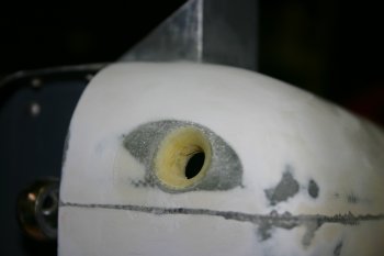
|
|
| Also added a layer of 2oz glass over the rudder cable inlet. | 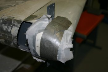
|
|
| Also added a final 2oz layer of glass over the rudder tip / wire duct. | 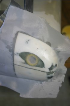
|
|
| Fibreglass clean up - a bit of sanding and all looks good. | 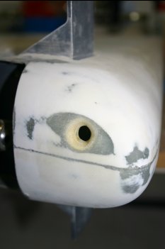
|
|
| Spent a few hours slowly cleaning masking tape off the rudder. Advice - if you use masking tape - remove it as soon as practical! I know the canopy is still a problem, but otherwise I'm finally done with most of the AL cleaning. We just used lots of acetone in the end. | 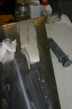
|
|
| | 
|


